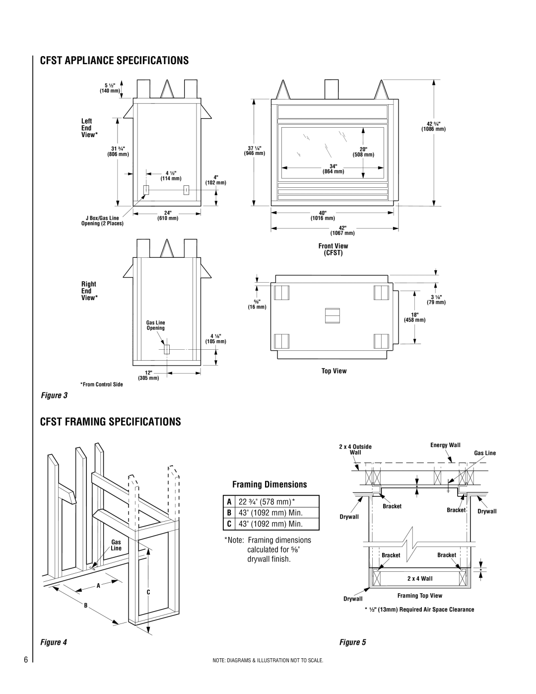
CFST APPLIANCE SPECIFICATIONS
5 ¹⁄₂"
(140 mm)
Left
End
View*
31³⁄₄"
(806 mm)
![]() 4 ¹⁄₂" (114 mm)
4 ¹⁄₂" (114 mm)
37 ¹⁄₄"
(946 mm)
4"
(102 mm)
20" |
(508 mm) |
34" |
(864 mm) |
42³⁄₄"
(1086 mm)
J Box/Gas Line |
|
| 24" |
|
| 40" |
|
|
| ||||
|
| (610 mm) | (1016 mm) | |||
Opening (2 Places)
42" (1067 mm)
Front View
(CFST)
Right
End
View*
*From Control Side
Figure 3
Gas Line
Opening
12"
(305 mm)
⁵⁄₈"
(16 mm)
4¹⁄₈"
(105 mm)
Top View
3 ¹⁄₈"
(79 mm)
18"
(458 mm)
CFST FRAMING SPECIFICATIONS
Framing Dimensions
2 x 4 Outside | Energy Wall |
Wall | Gas Line |
* |
Gas
Line
A22 ³⁄₄" (578 mm)* B 43" (1092 mm) Min. C 43" (1092 mm) Min.
*Note: Framing dimensions calculated for ⁵⁄₈"
Bracket
Drywall
Bracket Drywall
A
C
B
drywall finish.
BracketBracket
*
| 2 x 4 Wall |
Drywall | Framing Top View |
|
* ¹⁄₂" (13mm) Required Air Space Clearance
6
Figure 4 | Figure 5 |
| NOTE: DIAGRAMS & ILLUSTRATION NOT TO SCALE. |