Contents
2004
Users Guide
Important Notice
Page
July
How to Use This Manual
Read This First
About This Manual
Related Documentation From Texas Instruments
Information About Cautions and Warnings
FCC Warning
If You Need Assistance
Page
Contents
Frequently Asked Questions
Tables
Figures
Page
Topic
Get Started Now
Kit Contents, MSP-FET430X110
Kit Contents, MSP-FET430UIF
Software Installation
Hardware Installation, MSP-FET430X110
Flashing the LED
Hardware Installation, USB-IF, MSP-FET430UIF
Get Started Now
Important MSP430 Documents on the CD-ROM and WEB
Development Flow
Overview
Using Kickstart
OUTPUT-OUTPUT FILE-EXECUTABLE
Project Settings
Factory Settings
Creating a Project from Scratch
Stack Management within the .xcl Files
Using an Existing IAR V1.x/V2.x Project
Overview of Example Programs
How to Generate Texas Instrument .TXT and other format Files
Development Flow
Using C-SPY
Using Breakpoints
Breakpoint Types
Using Single Step
Using Watch Windows
Page
Design Considerations for In-Circuit Programming
External Power
Bootstrap Loader
Design Considerations for In-Circuit Programming
PRGS430
Device Signals
Design Considerations for In-Circuit Programming
Signal connections for MSP-FET430X110
Design Considerations for In-Circuit Programming
Jtag Signal Connections
Frequently Asked Questions
Hardware
Program Development Assembler, C-Compiler, Linker
Should Done or Not Return Omit
OPTIONS-FET DEBUGGER-CONNECTIONS
Debugging C-SPY
Frequently Asked Questions
Figure A-1. Modification to FET Interface module
Frequently Asked Questions
Frequently Asked Questions
Frequently Asked Questions
Frequently Asked Questions
Frequently Asked Questions
Hardware
Figure B-1. MSP-FET430X110, Schematic
Figure B-1. MSP-FET430X110, Schematic
Figure B-2. MSP-FET430X110, PCB Pictorials
Figure B-3. MSP-FET430IF FET Interface module, Schematic
Figure B-4. MSP-FET430IF FET Interface module, PCB Pictorial
Figure B-5. MSP-TS430DW28 Target Socket module, Schematic
LED connected to P1.0
Hardware
Jumper J7 Jumper J6Open to measure current
Hardware
Jumper J6 Open to disconnect LED
History of changes to MSP-TS430PM64 Target Socket module
Figure B-11. MSP-TSPN80 Target Socket module, Schematic
Figure B-12. MSP-TSPN80 Target Socket module, PCB Pictorials
Figure B-13. MSP-TSPZ100 Target Socket module, Schematic
Jumper J6
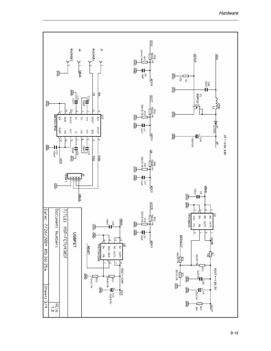
Figure B-15. MSP-FET430UIF USB Interface schematics
Hardware
Hardware
Hardware
Hardware
Page
FET Specific Menus
Emulator
EMULATOR-POWER on Reset
EMULATOR-FORCE Single Stepping
EMULATOR-GIE on/off
Pin MSP430F44x and MSP430F43x Device Emulation
Table D-1. F4xx/80-pin Signal Mapping
P1.5/TACLK/ACLK P1.4/TBCLK/SMCLK P1.3/TBOUTH/SVSOUT
Page
TI to IAR 2.x/3.x Assembler Migration
Translating Asm430 Assembler Directives to A430 Directives
Segment Control
Introduction
Character strings
Description Asm430 Directive TI A430 Directive IAR
Section Control Directives
Listing Control Directives
Constant Initialization Directives
File Reference Directives
Conditional-Assembly Directives
Reptc
Symbol Control Directives
Macro Directives
Miscellaneous Directives
Preprocessor Directives
Asm430 directive A430 directive
Additional A430 Directives IAR
Lstpag + #if, #else, #elif
Page
MSP-FET430UIF Installation Guide
Figure F-1. WinXP Hardware Recognition
Hardware Installation
Figure F-3. WinXP Driver Location Selection Folder
Figure F-4. WinXP Driver Installation
Figure F-5. Device Manager