Hardware
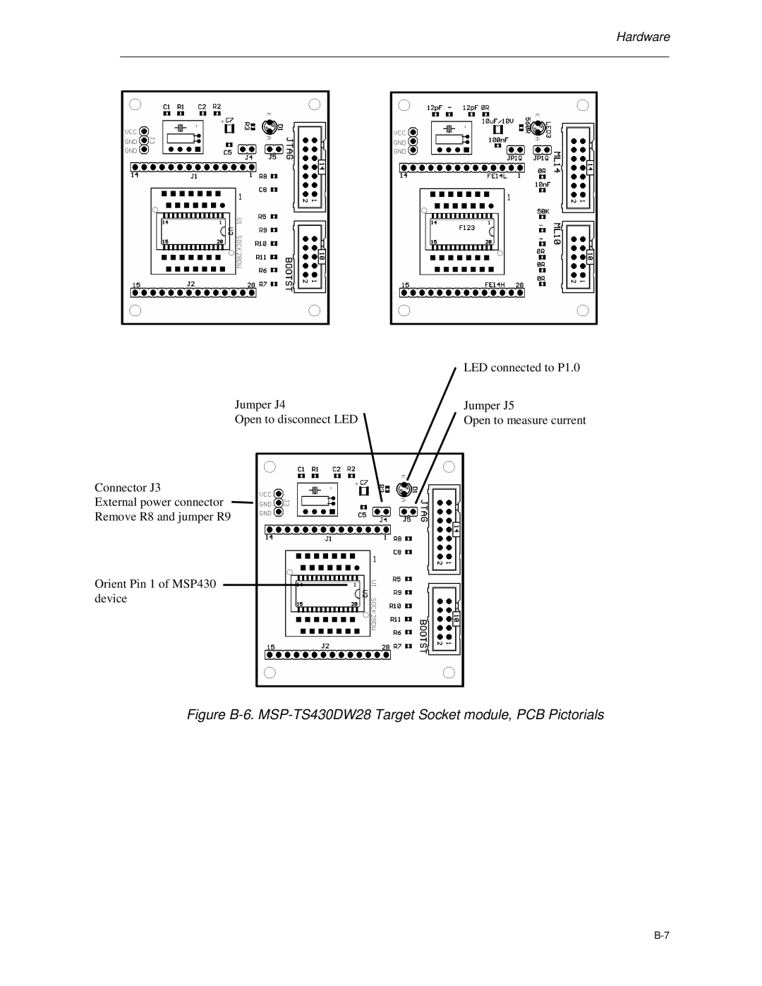
| LED connected to P1.0 |
Jumper J4 | Jumper J5 |
Open to disconnect LED | Open to measure current |
Connector J3
External power connector
Remove R8 and jumper R9
Orient Pin 1 of MSP430 device
Hardware
| LED connected to P1.0 |
Jumper J4 | Jumper J5 |
Open to disconnect LED | Open to measure current |
Connector J3
External power connector
Remove R8 and jumper R9
Orient Pin 1 of MSP430 device