www.ti.com | TLV320AIC3107EVM Software |
4.7GPIO1 Tab
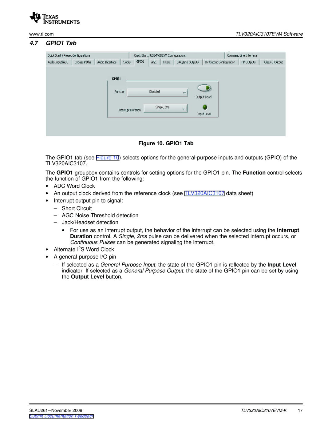
Figure 10. GPIO1 Tab
The GPIO1 tab (see Figure 10) selects options for the
The GPIO1 groupbox contains controls for setting options for the GPIO1 pin. The Function control selects the function of GPIO1 from the following:
∙ADC Word Clock
∙An output clock derived from the reference clock (see TLV320AIC3107 data sheet)
∙Interrupt output pin to signal:
–Short Circuit
–AGC Noise Threshold detection
–Jack/Headset detection
∙For use as an interrupt output, the behavior of the interrupt can be selected using the Interrupt Duration control. A Single, 2ms pulse can be delivered when the selected interrupt occurs, or Continuous Pulses can be generated signaling the interrupt.
∙Alternate I2S Word Clock
∙A
–If selected as a General Purpose Input, the state of the GPIO1 pin is reflected by the Input Level indicator. If selected as a General Purpose Output, the state of the GPIO1 pin can be set by using the Output Level button.
17 |
Submit Documentation Feedback
