The combustion air inlet can be installed through the either the lower left side casing
C. DRAFT REGULATORS:
A draft regulator is supplied with the furnace and should be installed according to the regulator manufacturers recommendations. With the burner operating, use a draft gauge to adjust the regulator to the proper setting. (refer to the instructions enclosed with draft regulator to adjust to the proper setting). When the burner air supply and draft are properly adjusted, the overfire draft should be a negative
Note: Draft overfire may be positive for high fire applications but not to exceed (+).02" WC.
D. DUCT WORK/AIR CONDITIONING:
If the furnace is used in connection with summer air conditioning (cooling), the furnace should be installed parallel with or on the upstream side of the evaporator coil to avoid condensation in the furnace heat exchanger. If the cooling unit is installed with a parallel flow arrangement, dampers or other means used to control flow of air should be provided to prevent chilled air from entering the furnace. If such a damper is manually operated, it must be equipped with a means to prevent operation of either unit, unless the damper is in the full heat or cool position.
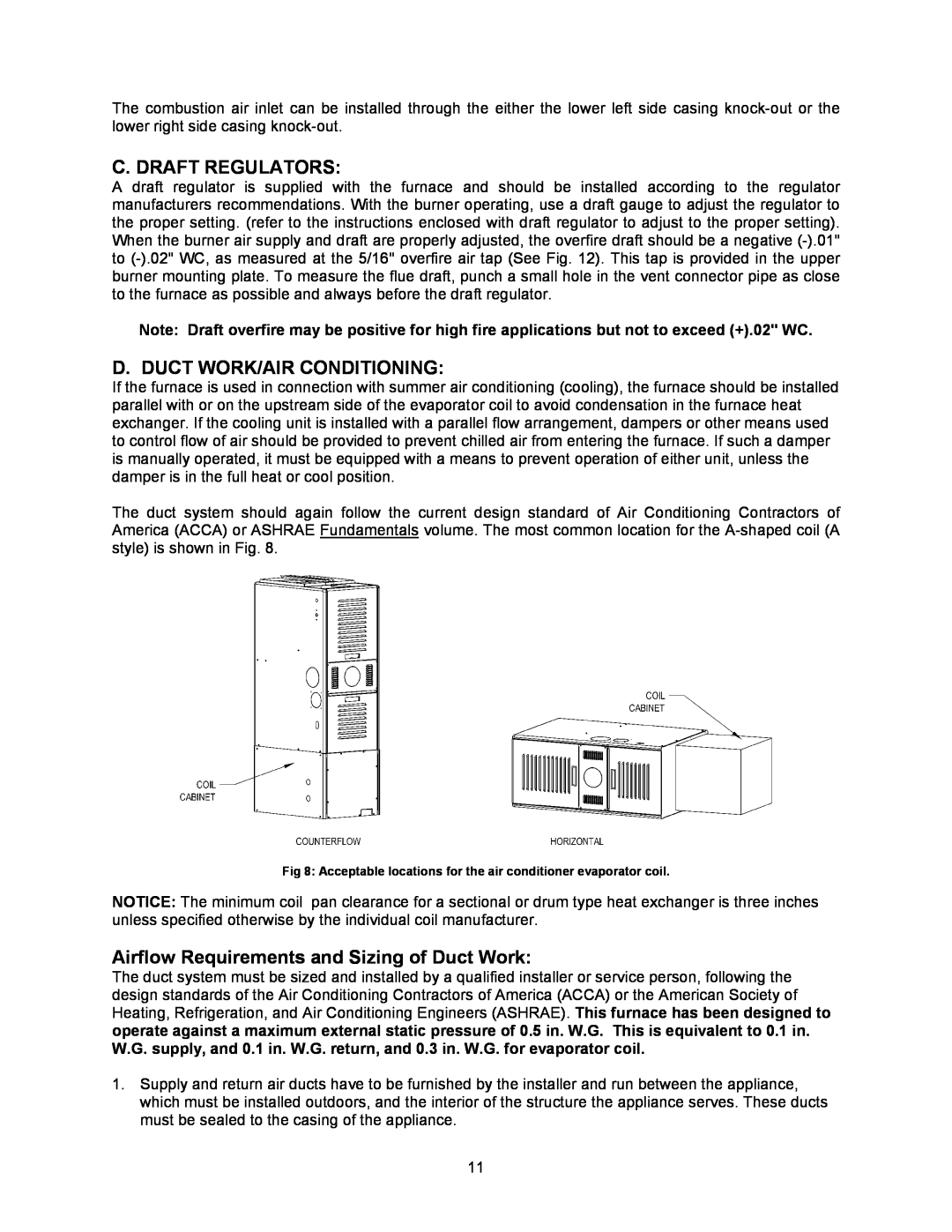
The duct system should again follow the current design standard of Air Conditioning Contractors of America (ACCA) or ASHRAE Fundamentals volume. The most common location for the
Fig 8: Acceptable locations for the air conditioner evaporator coil.
NOTICE: The minimum coil pan clearance for a sectional or drum type heat exchanger is three inches unless specified otherwise by the individual coil manufacturer.
Airflow Requirements and Sizing of Duct Work:
The duct system must be sized and installed by a qualified installer or service person, following the design standards of the Air Conditioning Contractors of America (ACCA) or the American Society of Heating, Refrigeration, and Air Conditioning Engineers (ASHRAE). This furnace has been designed to operate against a maximum external static pressure of 0.5 in. W.G. This is equivalent to 0.1 in. W.G. supply, and 0.1 in. W.G. return, and 0.3 in. W.G. for evaporator coil.
1.Supply and return air ducts have to be furnished by the installer and run between the appliance, which must be installed outdoors, and the interior of the structure the appliance serves. These ducts must be sealed to the casing of the appliance.
11