Manuals
/
Thermo Products
/
Household Appliance
/
Furnace
Thermo Products
ome-72d36 service manual
Models:
ome-72d36
1
48
48
Download
48 pages
32.75 Kb
41
42
43
44
45
46
47
48
<
>
Troubleshooting
Specification
Install
Wiring Diagram
Maintenance
Figure J. ELECTRICAL WIRING
Note Check diagnostic code through view port
AUX LIMIT NOT SHOWN BLOWER SUB-ASSEMBLY OME-72D36
B.Cad Cell Checkout Procedure
L.Burner Operation And Adjustment
Page 48
Image 48
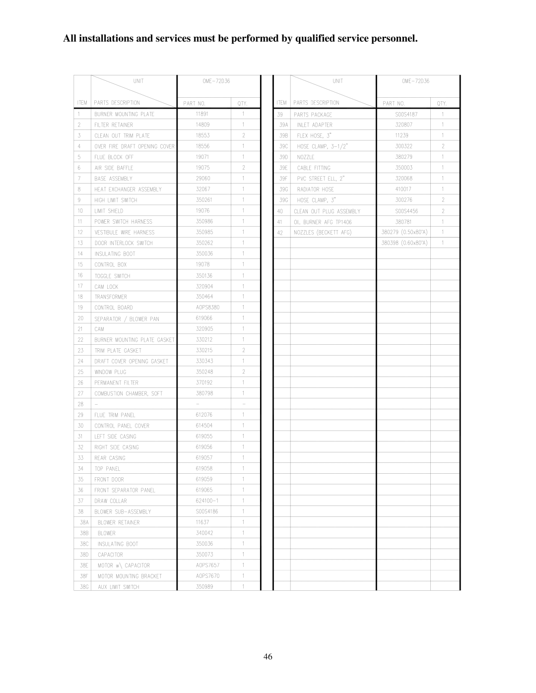
All installations and services must be performed by qualified service personnel.
46
Page 47
Page 48
Image 48
Page 47
Contents
FOR YOUR SAFETY
OIL-FIREDFURNACE
DOWN FLOW & DIRECT VENT SEALED COMBUSTION
WHAT TO DO IF YOU SMELL GAS
I. SAFETY SECTION
If you do not follow these instructions exactly, a fire or explosion may result causing personal injury, loss of life or property damage
Do not attempt to start the burner when
All installations and services must be performed by qualified service personnel
Page
TABLE OF CONTENTS
SECTION
BEGINNING PAGE
a. Combustible material
b.Non-combustiblematerial
MODELS OME
III. FURNACE SPECIFICATIONS
MODEL
OME-72
BURNER DATA
BLOWER DATA
IV. INSTALLATION A. ROOF JACK
B. STANDARD CHIMNEY
C.FURNACE LOCATION
D. BASE INSTALLATION
Combustible Floor Base Model 70-BASE
Cottage Base Model 01COT-BASE
Figure 1A
Page
2. Cottage Base Model 01COT-BASE
IMPORTANT Adequate combustion air must be provided under all circumstances. If the underside of the home is skirted or enclosed e.g. by an enclosed crawlspace, the combustion air intake should exit through the side of cottage base and terminate outside of the structure. All joints and seams of supply ducts and combustion air ducts must be closed with a sealing method suitable to the application conditions and temperatures e.g. using high temperature silicone caulk and/or aluminum tape
E. ALCOVE INSTALLATION
F.CLOSET INSTALLATION
G. COMBUSTION AIR
The preferred location of the outside combustion air intake termination e.g. an optional stainless steel intake hood, part no.370183 is through the side of the structure, skirting or enclosure. An alternate termination location is under the structure in the skirted or crawlspace area providing a minimum of 50 square inches of free area exists around the perimeter for outside combustion air to be drawn through. NOTE Combustion air cannot be drawn from the occupied space of the home
Page
H. FUEL PIPING
condensate, which causes the tank to rust. It is also recommended to use a water trap or additives to prevent condensate accumulation
Figure J. ELECTRICAL WIRING
1.Electrical Branch Supply Circuit
4. BLOWER CONTROLLER INFORMATION FOR PSC MOTOR
TERMINAL DEFINITIONS & FIELD WIRING
A. Inputs
B. Outputs
C. Operating Modes
Heat Mode
PSC TROUBLE SHOOTING
DIAGNOSTIC FEATURES
WIRING DIAGRAM
K. BURNER INSTALLATION
L.BURNER OPERATION AND ADJUSTMENT
a.Carbon dioxide CO2 or oxygen O2 analyzer
Page
M. FLUE GAS COMBUSTION ANALYSIS
BURNER COMBUSTION PARAMETERS
V. DEALER MAINTENANCE
A. TROUBLESHOOTING
TROUBLESHOOTING FLOWCHART
Note Check diagnostic code through view port
Correct wire connections
ignition electrodes? Yes
No Is oil present in the fuel line at the valve?
Check all wiring for
B.CAD CELL CHECKOUT PROCEDURE
C.HEAT EXCHANGER CLEANING INSTRUCTIONS
To vacuum and brush the outer radiator of the heat exchanger, go through the cleanout openings in both directions, as shown in Figure
D. CLEANING OR REPLACING FLUE PIPES
E. EXTENDED SHUTDOWN
VI. USER INFORMATION SECTION
A. WARNINGS AND CAUTIONS
B. COMPONENT LOCATIONS
Figure C. INSPECTION AREAS
D.FILTER LOCATION AND CLEANING
INSTALLATION / SERVICE
E. CONTACT INFORMATION
POWER HARNESS
AUX LIMIT NOT SHOWN BLOWER SUB-ASSEMBLY OME-72D36
ITEMS NOT SHOWN
VESTIBULE HARNESS