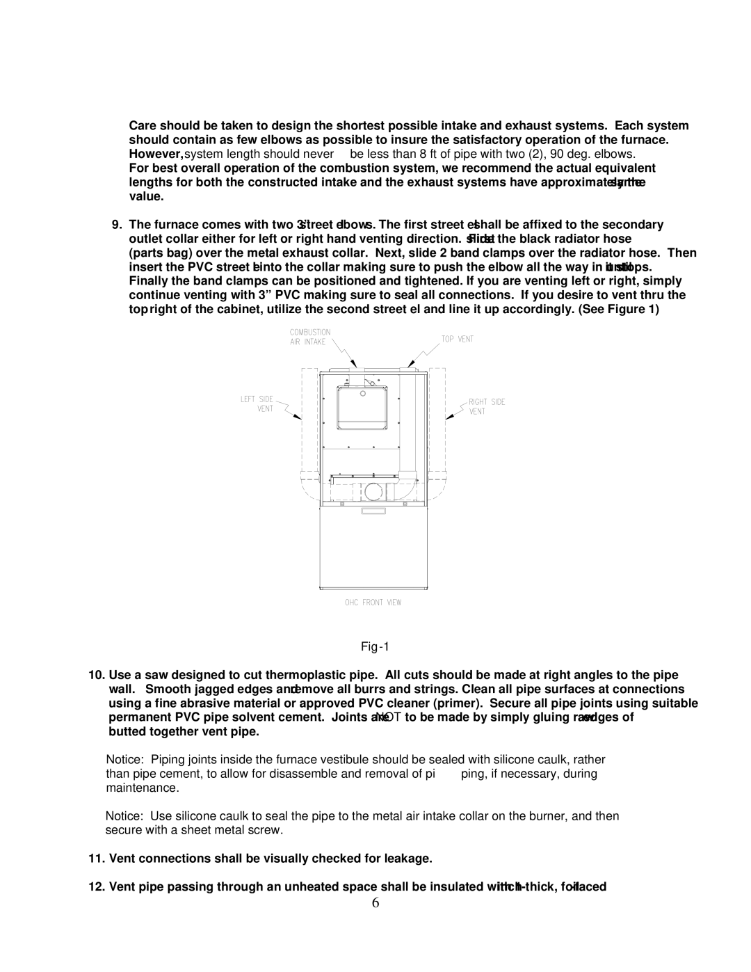
PHCFA072DV4R specifications
The Thermo Products PHCFA072DV4R is a cutting-edge heating and cooling solution designed for modern residential and light commercial applications. This unit stands out due to its efficient performance and advanced technology. One of the most remarkable features of the PHCFA072DV4R is its energy efficiency. It boasts a high SEER rating that ensures reduced energy consumption without sacrificing comfort, making it an environmentally friendly choice for homeowners.This system utilizes an inverter-driven compressor, which allows for variable speed operation. This means that the unit can adjust its output to match the specific heating or cooling needs of a space, providing more consistent temperatures and enhanced comfort. Additionally, this inverter technology minimizes noise levels, making the PHCFA072DV4R a quieter option compared to traditional fixed-speed systems.
Another noteworthy characteristic of the PHCFA072DV4R is its advanced filtration system. It is equipped with high-efficiency filters that effectively capture dust, pollen, and other airborne particles, ensuring improved indoor air quality. For those who suffer from allergies or have respiratory issues, this feature can provide significant relief.
The unit offers a user-friendly interface with a smart thermostat that enables users to control the system remotely. Through a mobile app, homeowners can adjust settings, set schedules, and monitor energy usage from anywhere, which adds a layer of convenience to the overall user experience.
Additionally, the PHCFA072DV4R is built with durability in mind. Its robust construction and high-quality materials ensure long-term reliability, reducing the likelihood of costly repairs. It also comes with a warranty that reflects the manufacturer's confidence in the product's performance.
Overall, the Thermo Products PHCFA072DV4R encapsulates efficiency, comfort, and advanced technology in a single package. Its ability to adapt to varying conditions, combined with features focused on air quality and ease of use, make it a prime choice for anyone looking for a versatile heating and cooling solution. This unit not only meets the demands of today's consumers but also aligns with sustainable practices, making it an ideal addition to any home or business.

