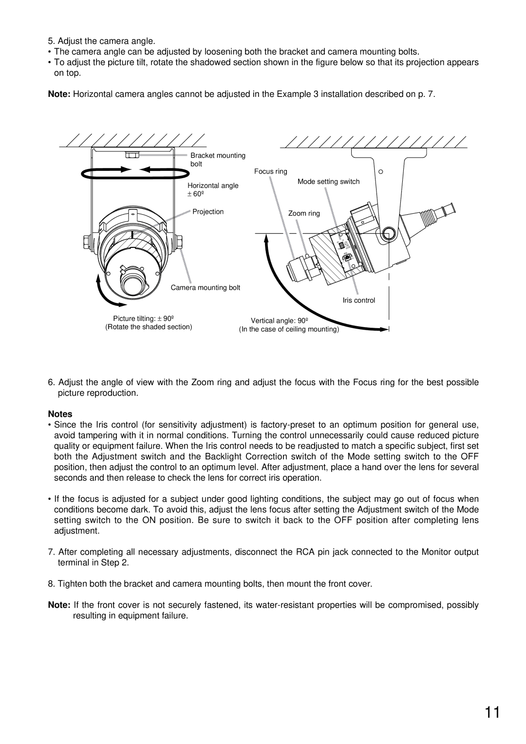
5. Adjust the camera angle.
•The camera angle can be adjusted by loosening both the bracket and camera mounting bolts.
•To adjust the picture tilt, rotate the shadowed section shown in the figure below so that its projection appears on top.
Note: Horizontal camera angles cannot be adjusted in the Example 3 installation described on p. 7.
![]() Bracket mounting bolt
Bracket mounting bolt
Focus ring
Horizontal angle
±60º
Mode setting switch
Projection | Zoom ring |
OFF | ON | J |
F.AD | ||
|
| BLC |
|
| 1/100 |
1/60 |
| SHUTTER |
| IRIS | |
L ![]()
H
Camera mounting bolt
| Iris control | |
Picture tilting: ± 90º | Vertical angle: 90º | |
(Rotate the shaded section) | ||
(In the case of ceiling mounting) | ||
|
6.Adjust the angle of view with the Zoom ring and adjust the focus with the Focus ring for the best possible picture reproduction.
Notes
•Since the Iris control (for sensitivity adjustment) is
•If the focus is adjusted for a subject under good lighting conditions, the subject may go out of focus when conditions become dark. To avoid this, adjust the lens focus after setting the Adjustment switch of the Mode setting switch to the ON position. Be sure to switch it back to the OFF position after completing lens adjustment.
7.After completing all necessary adjustments, disconnect the RCA pin jack connected to the Monitor output terminal in Step 2.
8.Tighten both the bracket and camera mounting bolts, then mount the front cover.
Note: If the front cover is not securely fastened, its
11