10. STACKING
10.1. General Description
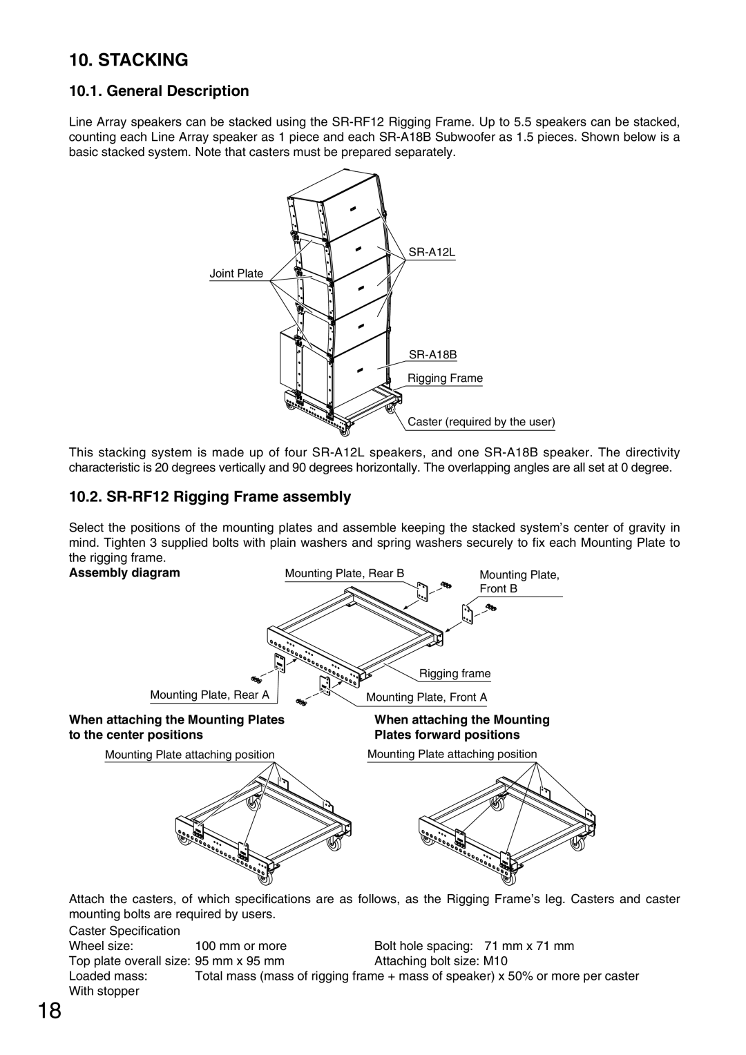
Line Array speakers can be stacked using the
Joint Plate
Rigging Frame
Caster (required by the user)
This stacking system is made up of four
10.2. SR-RF12 Rigging Frame assembly
Select the positions of the mounting plates and assemble keeping the stacked system’s center of gravity in mind. Tighten 3 supplied bolts with plain washers and spring washers securely to fix each Mounting Plate to the rigging frame.
Assembly diagram | Mounting Plate, Rear B | Mounting Plate, |
|
| Front B |
Mounting Plate, Rear A
When attaching the Mounting Plates to the center positions
Mounting Plate attaching position
Rigging frame
Mounting Plate, Front A
When attaching the Mounting Plates forward positions
Mounting Plate attaching position
Attach the casters, of which specifications are as follows, as the Rigging Frame’s leg. Casters and caster mounting bolts are required by users.
Caster Specification |
|
|
Wheel size: | 100 mm or more | Bolt hole spacing: 71 mm x 71 mm |
Top plate overall size: 95 mm x 95 mm | Attaching bolt size: M10 | |
Loaded mass: | Total mass (mass of rigging frame + mass of speaker) x 50% or more per caster | |
With stopper |
|
|
18