Chapter 2 — Belts, Controls and Linkages
INTRODUCTION
All models use two belts. One to drive the auger and a second to drive the traction system. The auger drive uses a combination idler and brake to engage the belt for driving and to disengage the belt and apply the brake for stopping.
The traction drive uses a constantly tensioned belt. The clutching and shifting are done through the drive plate and friction disc.
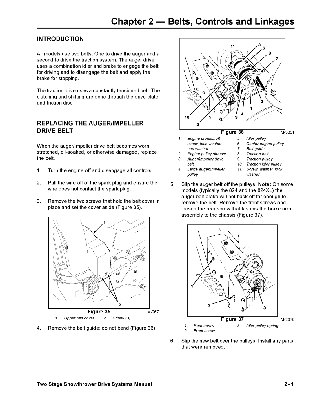
REPLACING THE AUGER/IMPELLER DRIVE BELT
When the auger/impeller drive belt becomes worn, stretched,
1.Turn the engine off and disengage all controls.
2.Pull the wire off of the spark plug and ensure the wire does not contact the spark plug.
3.Remove the two screws that hold the belt cover in place and set the cover aside (Figure 35).
|
|
|
| 3331 | |
|
| Figure 36 | M- | ||
1. | Engine crankshaft | 5. | Idler pulley | ||
|
| screw, lock washer | 6. | Center engine pulley | |
|
| and washer | 7. | Belt guide | |
2. | Engine pulley sheave | 8. | Traction belt | ||
3. | Auger/impeller drive | 9. | Traction pulley | ||
|
| belt | 10. | Traction idler pulley | |
4. | Large auger/impeller | 11. | Screw, washer, lock | ||
|
| pulley |
| washer | |
5.Slip the auger belt off the pulleys. Note: On some models (typically the 824 and the 824XL) the auger belt brake will not back off far enough to remove the belt. Remove the front screws and loosen the rear screw that fastens the brake arm assembly to the chassis (Figure 37).
|
|
|
|
Figure 35 | |||
1. Upper belt cover | 2. | Screw (3) | |
4.Remove the belt guide; do not bend (Figure 36).
|
|
|
|
|
|
| Figure 37 |
| |
1. Rear screw | 3. | Idler pulley spring | ||
2.Front screw
6.Slip the new belt over the pulleys. Install any parts that were removed.
Two Stage Snowthrower Drive Systems Manual | 2 - 1 |
