Belts, Controls and Linkages
Adjusting the Traction Control — 824XL (Toro Models 38066, 38078, 38083, 38084, 38086 and
1.Slide spring onto bottom of traction control rod (Figure 59).
|
|
|
|
|
| Figure 59 |
| ||
1. Traction control rod | 3. | Flange lock nut | ||
2.Spring
2.Thread a flange lock nut (flange side up) onto bottom of traction control rod below spring.
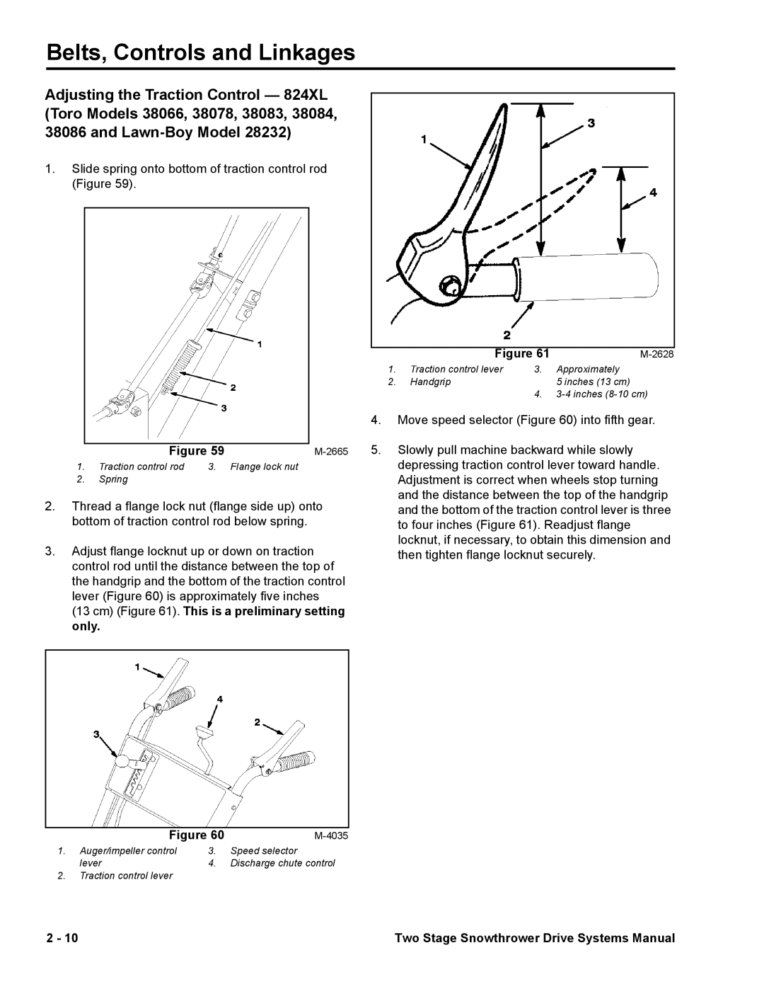
3.Adjust flange locknut up or down on traction control rod until the distance between the top of the handgrip and the bottom of the traction control lever (Figure 60) is approximately five inches
(13 cm) (Figure 61). This is a preliminary setting only.
|
|
|
|
| Figure 60 | ||
1. | Auger/impeller control | 3. | Speed selector |
| lever | 4. | Discharge chute control |
2. | Traction control lever |
|
|
|
|
| |
| Figure 61 | ||
1. | Traction control lever | 3. | Approximately |
2. | Handgrip |
| 5 inches (13 cm) |
|
| 4. | |
4.Move speed selector (Figure 60) into fifth gear.
5.Slowly pull machine backward while slowly depressing traction control lever toward handle. Adjustment is correct when wheels stop turning and the distance between the top of the handgrip and the bottom of the traction control lever is three to four inches (Figure 61). Readjust flange locknut, if necessary, to obtain this dimension and then tighten flange locknut securely.
2 - 10 | Two Stage Snowthrower Drive Systems Manual |
