Traction Drive Systems
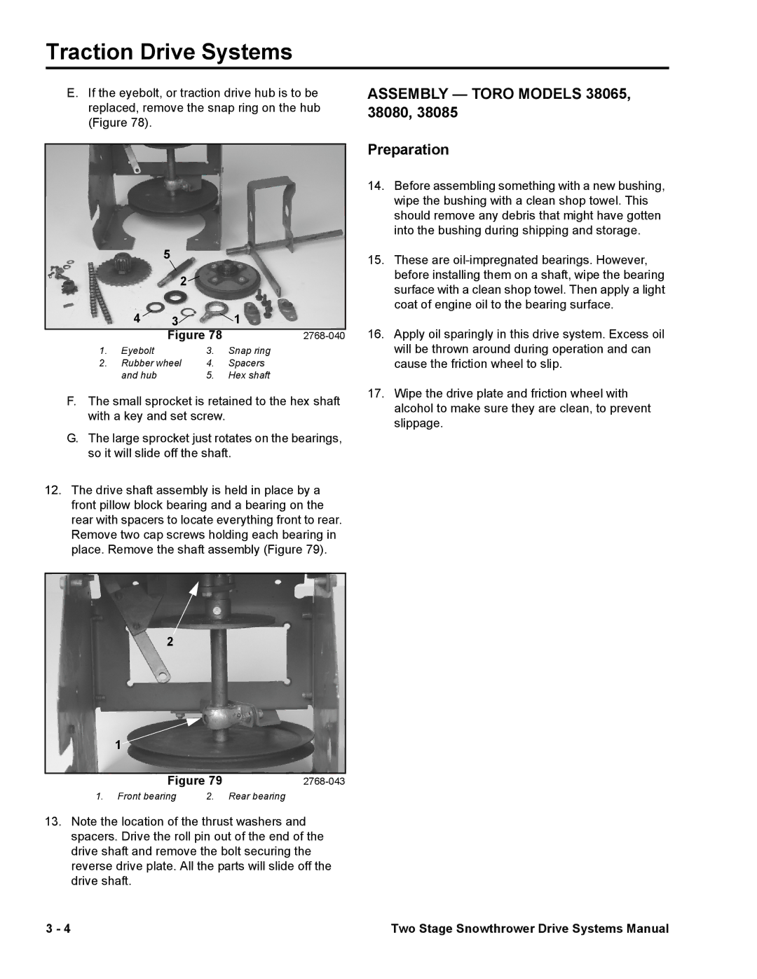
E.If the eyebolt, or traction drive hub is to be replaced, remove the snap ring on the hub (Figure 78).
5
| 2 |
|
|
4 | 3 |
| 1 |
| Figure 78 | ||
1. Eyebolt |
| 3. | Snap ring |
2. Rubber wheel | 4. | Spacers | |
and hub |
| 5. | Hex shaft |
F.The small sprocket is retained to the hex shaft with a key and set screw.
G.The large sprocket just rotates on the bearings, so it will slide off the shaft.
12.The drive shaft assembly is held in place by a front pillow block bearing and a bearing on the rear with spacers to locate everything front to rear. Remove two cap screws holding each bearing in place. Remove the shaft assembly (Figure 79).
2
1![]()
Figure 79 | ||
1. Front bearing | 2. | Rear bearing |
13.Note the location of the thrust washers and spacers. Drive the roll pin out of the end of the drive shaft and remove the bolt securing the reverse drive plate. All the parts will slide off the drive shaft.
ASSEMBLY — TORO MODELS 38065, 38080, 38085
Preparation
14.Before assembling something with a new bushing, wipe the bushing with a clean shop towel. This should remove any debris that might have gotten into the bushing during shipping and storage.
15.These are
16.Apply oil sparingly in this drive system. Excess oil will be thrown around during operation and can cause the friction wheel to slip.
17.Wipe the drive plate and friction wheel with alcohol to make sure they are clean, to prevent slippage.
3 - 4 | Two Stage Snowthrower Drive Systems Manual |