Belts, Controls and Linkages
ADJUSTING TRACTION CONTROL
Adjusting the Traction Control — Toro Models 38065, 38080, 38085
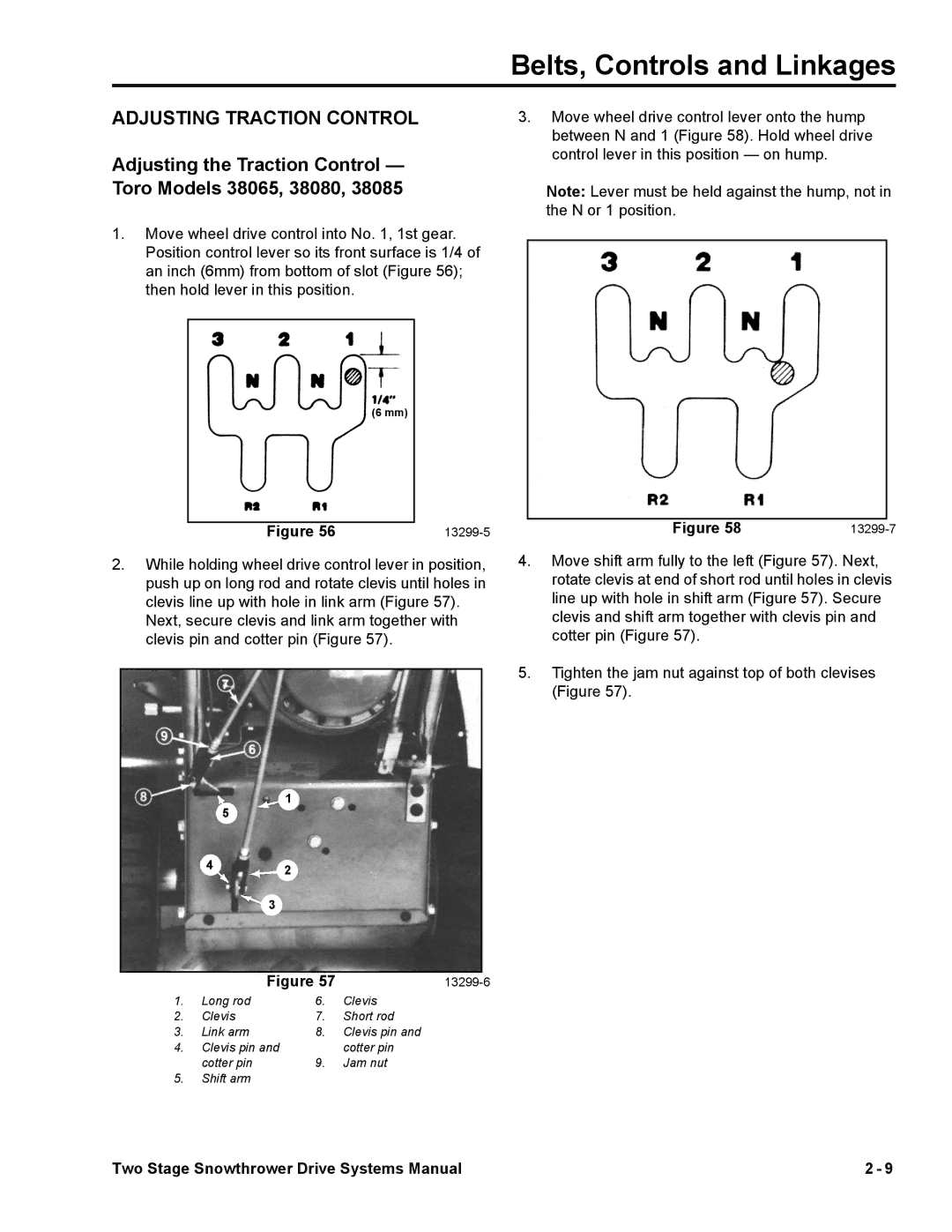
1.Move wheel drive control into No. 1, 1st gear. Position control lever so its front surface is 1/4 of an inch (6mm) from bottom of slot (Figure 56); then hold lever in this position.
(6 mm)
Figure 56 |
2.While holding wheel drive control lever in position, push up on long rod and rotate clevis until holes in clevis line up with hole in link arm (Figure 57).
Next, secure clevis and link arm together with clevis pin and cotter pin (Figure 57).
1
5
42
3
|
|
|
|
|
|
| Figure 57 | ||
1. | Long rod | 6. | Clevis | |
2. | Clevis | 7. | Short rod | |
3. | Link arm | 8. | Clevis pin and | |
4. | Clevis pin and | cotter pin | ||
| cotter pin | 9. | Jam nut | |
5.Shift arm
3.Move wheel drive control lever onto the hump between N and 1 (Figure 58). Hold wheel drive control lever in this position — on hump.
Note: Lever must be held against the hump, not in the N or 1 position.
|
|
|
Figure 58 | ||
4.Move shift arm fully to the left (Figure 57). Next, rotate clevis at end of short rod until holes in clevis line up with hole in shift arm (Figure 57). Secure clevis and shift arm together with clevis pin and cotter pin (Figure 57).
5.Tighten the jam nut against top of both clevises (Figure 57).
Two Stage Snowthrower Drive Systems Manual | 2 - 9 |
