Playback
Function Setup
Owner’s Record
1VMN27813 / E9PG0CD
Additional Safety Instructions
Precautions
Symbol for Class ll Double Insulation
Location and Handling
Precautions
Avoid a place with drastic temperature changes
To Avoid the Hazards of Electrical Shock and Fire
Dew Condensation Warning
Installation Location
Supplied Accessories
IR Signal Check
Cleaning the Disc Lens Disc Handling
Maintenance Servicing
Cleaning the Cabinet
Cleaning Discs
Contents
Contents
Features
Features
Region Codes
Unplayable Discs
Color Systems
Introduction Connections
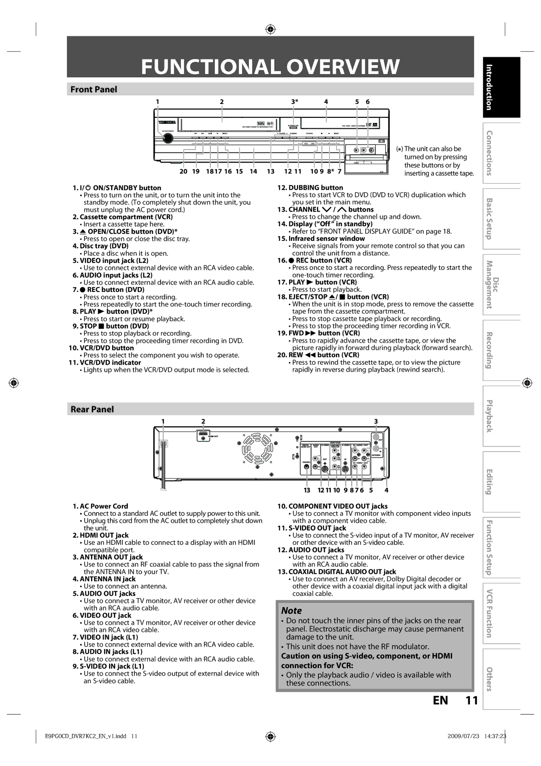
Functional Overview
Front Panel
Rear Panel
Open the cover Insert batteries
Installing the Batteries in the Remote Control
Using a Remote Control
Functional Overview
Setup button
Using a Remote Control cont’d
Thevcr / DVD Recorder Switching
MP3/WMA Tag Information
On-Screen Display / Menu
Disc Information/Menu Title Name Information
File Name Information
File name information
Guide to ON-SCREEN Displays and Menus
On-Screen Display / Menu cont’d
Title name information
Main Menu
Current status of the unit
This is a new Power Save ECO feature
Front Panel Display Guide
Display Message
Supplied cables used in this connection are as follows
Connection
Antenna Connection Required
Overview
Connection
Connecting to a TV Using Audio / Video Out Jacks
RF coaxial cable x RCA audio cable L/R x
Connecting to a TV Using the S-Video Out Jack
Connecting to a TV Using Component Video Out Jacks
Supplied cables used in this connection are as follows
Copyright protection system
Connecting to a TV with an Hdmi Compatible Port
Hdmi Video Resolution and Actual Output Signals
Make sure to select the appropriate input type by
Connecting to a Cable / Satellite Box
With this setup
After making the connection as described above
No supplied cables are used in these connections
Connecting to a TV without Audio / Video Jacks
Digital Audio Connection
Dolby Digital Setting DTS Setting
To set up Dolby Digital, refer to pages 85, 87
Multi Channel Digital Audio Setting
Setting in the Setup Menu Actual Audio Output
Press Enter to activate Clock
Initial Setting
Proceed to in Manual Clock Setting on
Press Enter to start Channel
Auto Channel Scan
Channel Setting
When scanning is over, press Setup to exit
Use K / L to select Manual Channel
Channel Setting
Press Setup to exit
Adding/Deleting Channels
Manual Auto Clock Setting
Setting the Clock
Auto Clock Setting
Press Setup to exit and turn off
Daylight Saving Time
Setting the Clock
SAP secondary audio program
Selecting TV Audio
Enter
Use K / L to select TV Audio Select, then press Enter
Choosing the Recording Format of a Brand-New DVD-RW
Formatting a Disc
Use K / L to select Yes, then press Enter
VR mode DVD-RW
Formatting a Disc
Reformatting a Disc Manually
Disc will be protected
Setting a Disc to Protect
To cancel the disc protect
Auto Finalizing
Playingthe Discs in Other DVD Players
Finalizing is completed
Playing the Discs in Other DVD Players
Finalizing a Disc
Use K / L to select Finalize, then press Enter
Finalizing a Disc cont’d
To cancel finalizing DVD-RW only
Video
Recording Mode
Information on DVD Recording
Restrictions on Recording
Make Recording Compatible
Settings for a Recording
Setting for Auto Chapter
Press Setup to exit
Recording
Settings for a Recording
Setting Aspect Ratio for Video Mode
Recording Audio Select XP
Instructions continue on the next
Press I/y ON/STANDBY
Press OPEN/CLOSE a to close the disc tray
It may take awhile to load Disc completely
Will be displayed for 5 seconds
Basic Recording & ONE-TOUCH Timer Recording
Press REC I to start recording
Press Stop C to stop recording
Press B
Timer Recording
Use K / L to enter the date, then
Press Timer SET to set a timer programming
Timer Recording
Use K / L to select a recording mode
Press Enter when all items are entered
To stop the timer recording in progress
Priority of Overlapped Settings
Hints for Timer Recording
Supplied cables used in this connection are as follows
Settings for AN External Device
Connection to an External Device
External device
Recording from an External Device
Settings for AN External Device
Use K / L to select Recording, then press Enter
General Setting menu will appear
DVD/VCR Dubbing
Use K / L to select Dubbing
For DVD to VCR duplication
DVD/VCR Dubbing
Press Stop C to stop the recording
VCR to DVD DVD to VCR
Information on Playback
Structure of Disc Contents
Press Stop C once to stop playback temporarily
Refer to Using the Title/Disc Menu on
Basic Playback
Direct Playback
Use K / L to select Play From
Playback from the Title List
Press DVD
Title, then press Enter
Follow steps 1 to 2 in Direct Playback on
Basic Playback
Playing Back a DivX
When selecting file
Playing Back a DivX cont’d
Playback will be paused and sound will be muted
Using the Title/Disc Menu
Pause
Press DVD first During playback, press Pause F
40x REV 20x REV
Special Playback
Resume Playback
Fast Forward / Fast Reverse Playback
Slow Forward / Slow Reverse Playback
Special Playback
Rapid Playback
Step by Step Playback
Use / B to select to display the selection menu
Marker Setting
Zoom
Press DVD first During playback, press Display or Zoom
This unit start to record the TV broadcast
Chasing Playback during Recording
During recording, press Play B
While viewing a TV broadcast via this unit, press Time Slip
To move to for chapter, press B
Simultaneous Playback and Recording
Selected title playback will start
Chapter
Title/Chapter Search
Using Skip j / Skip
Using Display
Search
Audio CD
Search
Time Search
Random Playback
Repeat Playback
5Press Play B
REPEAT/RANDOM/PROGRAM PLAYBACK/SLIDE Show
Program Playback
Switching Audio Soundtrack
Switching Subtitles
Reducing Block Noise
Switching Virtual Surround System Switching Camera Angles
Selecting the Format of Audio and Video
Use K / L to select OFF or ON, then press Enter
Adjusting Black Level
Your setting will be activated
Use K / L to select Black Level, then press Enter
Guide to a Title List
Information on Disc Editing
After the disc is fully recorded
Deleting Titles
Stop mode, press TOP Menu
Deleting Titles
Use K / L to select Add To Playlist, then press Enter
CREATING/DELETING Playlist
Adding Titles to a Playlist
Original
Use K / L to select Yes, then press
Press DVD Press Setup
CREATING/DELETING Playlist
Erasing All Playlist
Stop mode, press TOP Menu
Editing Discs
Putting Names on Titles
To enter a title name, follow
Guide to Edit Title Name
Editing Discs
Putting Names on Titles cont’d
Press Return again and then Return or Stop C to exit
Setting Chapter Marks
Use Skip H / G
Press Return
Title, then press Enter
Hiding Chapters
Use K / L to select Edit, then press Enter
Use Skip H or Skip G to decide the chapter to be hidden
Deleting a Part of a Title
VR mode DVD-RW playlist
Press Return and then Return or Stop C to exit
Deleting a Part of a Title cont’d
Use K / L to select Delete then press Enter
Use K / L/s / B to select a desired title, then press Enter
Dividing a Title
Press DVD Stop mode, press TOP Menu
Two titles will combine into a single title
Combining Titles
You can combine two titles into a single title
Setting or Releasing the Title Protection
If you select OFF at , all the chapter marks are erased
Setting or Clearing All Chapter Marks at Once
Use K / L to select the desired interval, then press Enter
Setup Items highlight is the default Contents
List of the Default Settings
ONAPR-OCT OFF
List of the Default Settings
Press Stop C if you are playing back a disc
General Setting
Playback
Use K / L to select a desired item, then press Enter
Playback cont’d
General Setting
Parental Lock Default OFF
Use the Number buttons to enter the current password
Audio Out
Angle Icon Default on
Disc Menu Language Default English
Audio Language Default Original
Subtitle Language Default OFF
Display
OSD Language Default English
Screen Saver Default 10 minutes
FL Dimmer Default Bright
Selected item
Progressive Default OFF
TV Aspect Default 169 Wide
Video
Set the DivX subtitle
DivX Subtitle Default OFF
DivX
DivX VOD
Hdmi
Format Default RGB
Hdmi cont’d
Hdmi Audio Default on
Set to OFF when the Hdmi sound is not output
RGB Range Default Normal
Reset the setting to default
Reset All
Select Yes using K / L , then press Enter
Information on VCR Functions
Setup VCR Function Others
VCR Functions
VCR Functions
One-touch Timer Recording OTR
You cannot pause the one-touch timer recording
Using REC I or Stop C
Other Operations
Symptom Remedy
Troubleshooting
Troubleshooting
102 EN
Pages 23
Frequently Asked Questions
Can I record to CD-RW/-R?
Language Code
Language Code
Glossary
Input / Output
Specifications
General
Recording
Lplwhg 2QH � HDU DUUDQW\ RQ 3DUWV DQG /DERXU
Limited Warranty
$UELWUDWLRQ DQG Lvsxwh 5HVROXWLRQ
Limited Warranty
Memo