7. 4 E. TRG (External trigger)
Charge begins to accumulate after the trigger input to CC1 of the DIGITAL terminal, and 1 frame images are output. There are four modes: 1P SNR, 1P SR, PW SNR, PW SR.
( 1 ) 1P SNR (1 Pulse Trigger Sync Non Reset)
Charge begins to accumulate after the trigger input to CC1 of the DIGITAL terminal, and 1 frame images are output.
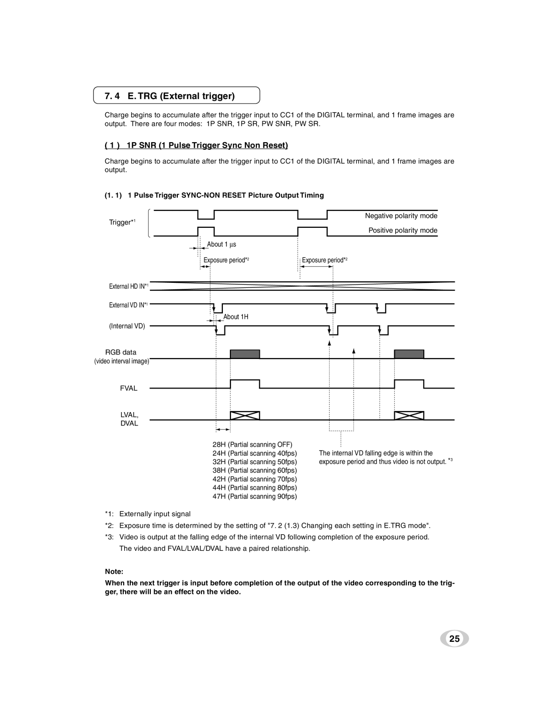
(1. 1) 1 Pulse Trigger SYNC-NON RESET Picture Output Timing
Trigger*1
External HD IN*1
External VD IN*1
(Internal VD)
RGB data (video interval image)
FVAL
LVAL,
DVAL
Negative polarity mode
Positive polarity mode
About 1 ∝s
Exposure period*2 | Exposure period*2 |
About 1H
28H | (Partial scanning OFF) |
|
24H | (Partial scanning 40fps) | The internal VD falling edge is within the |
32H | (Partial scanning 50fps) | exposure period and thus video is not output. *3 |
38H | (Partial scanning 60fps) |
|
42H | (Partial scanning 70fps) |
|
44H | (Partial scanning 80fps) |
|
47H | (Partial scanning 90fps) |
|
*1: Externally input signal
*2: Exposure time is determined by the setting of "7. 2 (1.3) Changing each setting in E.TRG mode".
*3: Video is output at the falling edge of the internal VD following completion of the exposure period. The video and FVAL/LVAL/DVAL have a paired relationship.
Note:
When the next trigger is input before completion of the output of the video corresponding to the trig- ger, there will be an effect on the video.
25