9 ELECTRIC WORK
Indoor unit power supply
(*1)
•For the power supply of the indoor unit, prepare the exclusive power supply separated from that of the outdoor unit.
•Arrange the power supply, earth leakage breaker, and main switch of the indoor unit connected to the same outdoor unit so that they are commonly used.
•Power supply cord specification : Cable
Indoor/Outdoor inter-unit wiring, Central controller wiring
(*2) (*3)
•
•To prevent noise trouble, use
•The length of the communication line means the total length of the
Remote controller wiring
(*4)
•
Remote controller wiring, remote | Twist wire: 0.5mm2 | to 2.0mm2 × 2 | |
controller | |||
|
| ||
|
|
|
Total wire length of remote controller | In case of wired type only | Up to 500m | |
wiring and remote controller |
|
| |
In case of wireless type included | Up to 400m | ||
wiring = L + L1 + L2 + … Ln | |||
|
|
| |
Total wire length of remote controller | Up to 200m | ||
|
|
| |
CAUTION
The remote controller wire (Communication line) and
Remote controller wiring
Indoor unit |
| Indoor unit |
| Indoor unit |
| Indoor unit |
|
|
|
|
|
|
|
| L1 |
| L2 | Ln | ||
Remote | Remote controller | (Max. 8 units) | ||||
controller |
|
| ||||
|
|
|
|
|
| |
|
|
|
|
|
|
|
Wiring connection
How to connect the power cable
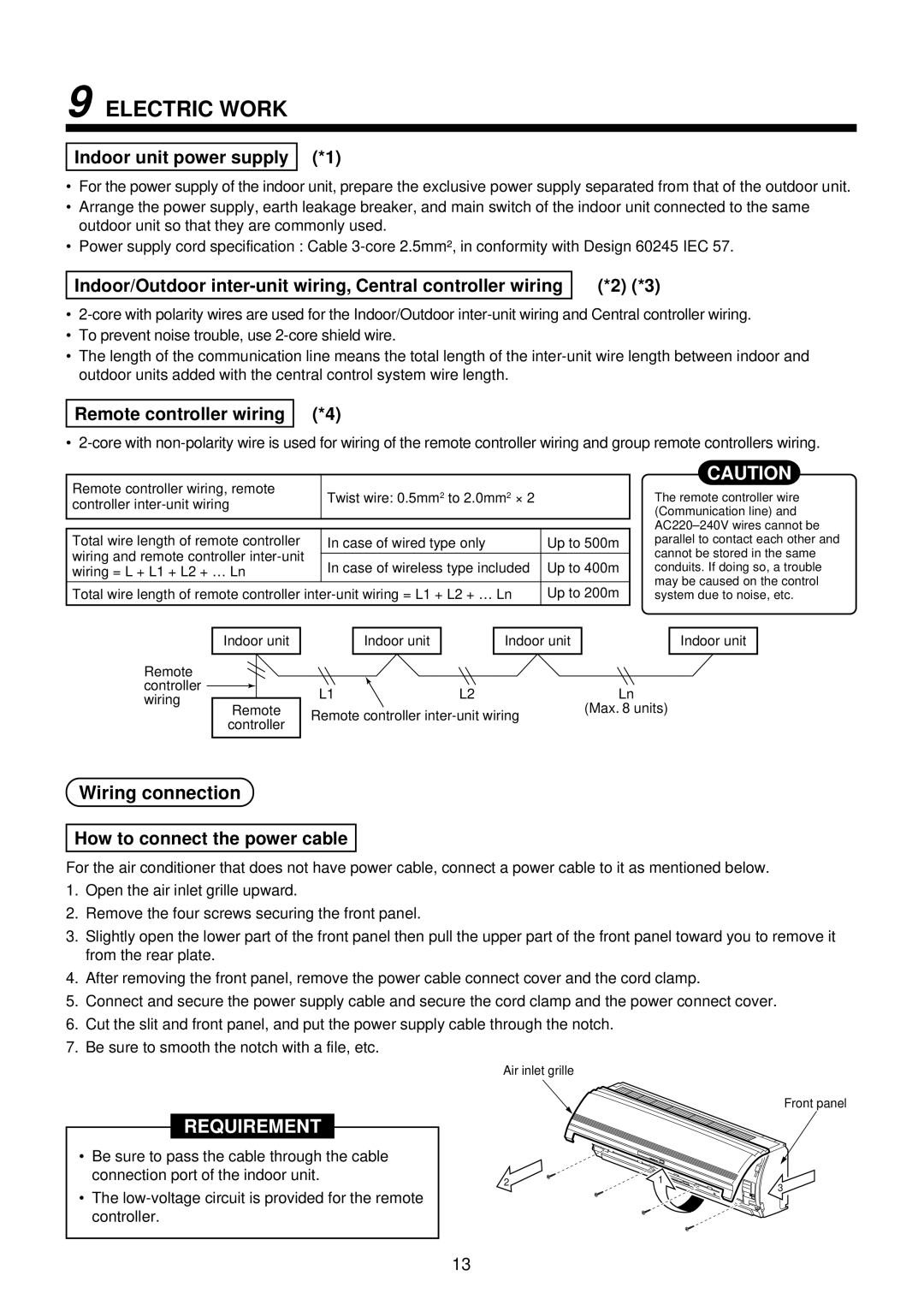
For the air conditioner that does not have power cable, connect a power cable to it as mentioned below.
1.Open the air inlet grille upward.
2.Remove the four screws securing the front panel.
3.Slightly open the lower part of the front panel then pull the upper part of the front panel toward you to remove it from the rear plate.
4.After removing the front panel, remove the power cable connect cover and the cord clamp.
5.Connect and secure the power supply cable and secure the cord clamp and the power connect cover.
6.Cut the slit and front panel, and put the power supply cable through the notch.
7.Be sure to smooth the notch with a file, etc.
Air inlet grille
Front panel
REQUIREMENT
•Be sure to pass the cable through the cable connection port of the indoor unit.
•The
2 | 1 |
| 3 |
13