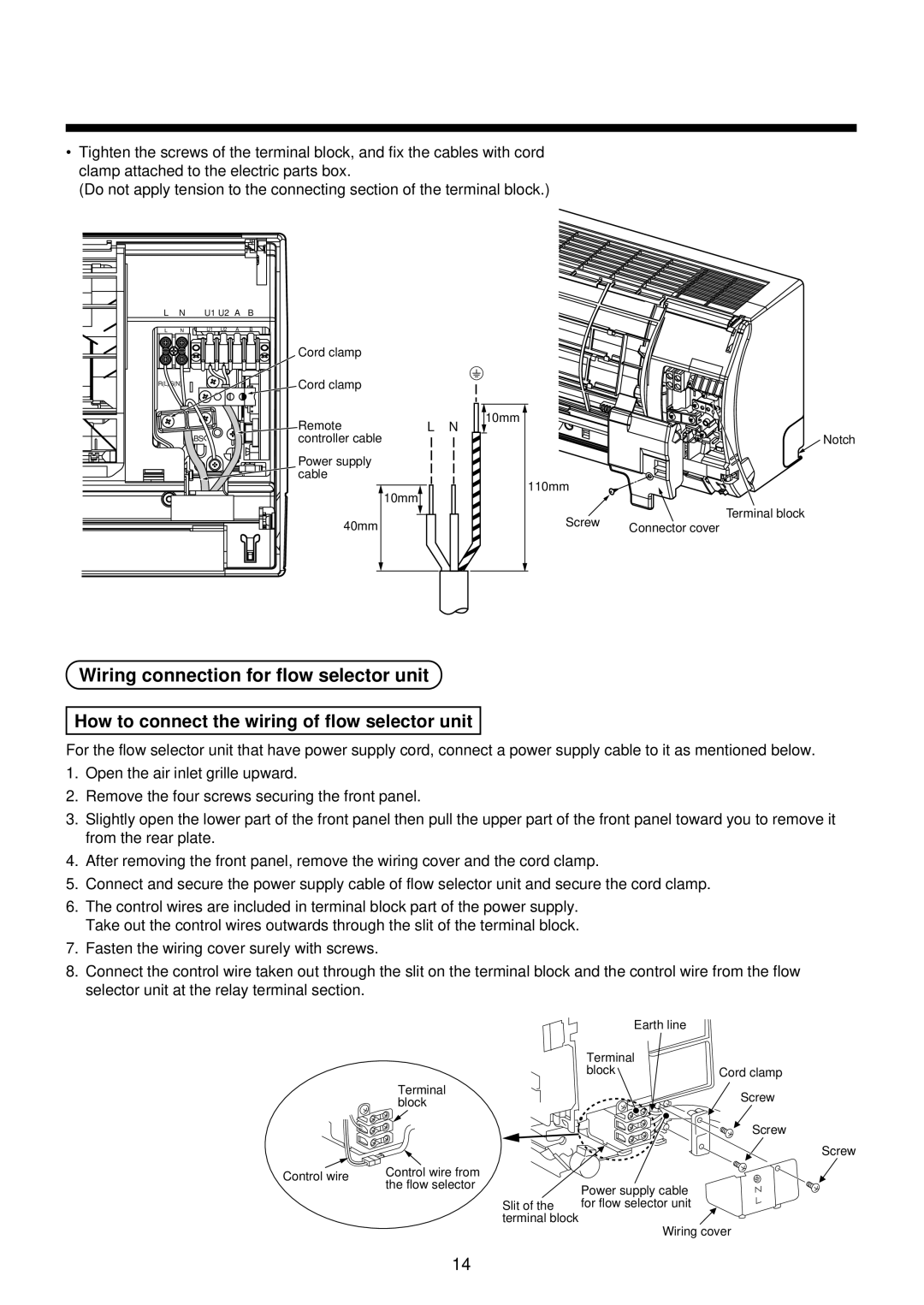
•Tighten the screws of the terminal block, and fix the cables with cord clamp attached to the electric parts box.
(Do not apply tension to the connecting section of the terminal block.)
L | N | U1 U2 A | B |
L | N | U1 U2 A | B |
R(L) S(N)
>ABS<
Cord clamp |
| |
Cord clamp |
| |
Remote | L N | |
controller cable |
| |
Power supply |
| |
cable |
| |
|
|
|
10mm
10mm
Notch
110mm
Terminal block
40mm
Screw | Connector cover |
|
Wiring connection for flow selector unit
How to connect the wiring of flow selector unit
For the flow selector unit that have power supply cord, connect a power supply cable to it as mentioned below.
1.Open the air inlet grille upward.
2.Remove the four screws securing the front panel.
3.Slightly open the lower part of the front panel then pull the upper part of the front panel toward you to remove it from the rear plate.
4.After removing the front panel, remove the wiring cover and the cord clamp.
5.Connect and secure the power supply cable of flow selector unit and secure the cord clamp.
6.The control wires are included in terminal block part of the power supply. Take out the control wires outwards through the slit of the terminal block.
7.Fasten the wiring cover surely with screws.
8.Connect the control wire taken out through the slit on the terminal block and the control wire from the flow selector unit at the relay terminal section.
|
| Earth line |
|
|
| Terminal |
|
|
| block | Cord clamp |
| Terminal |
| Screw |
| block |
| |
|
|
| |
|
|
| Screw |
|
|
| Screw |
Control wire | Control wire from |
|
|
the flow selector | Power supply cable |
| |
|
| ||
|
|
| |
| Slit of the | for flow selector unit |
|
| terminal block | Wiring cover | |
|
| ||
14
