FUNCTION OF I/O PANEL
(1) |
|
| (2) |
|
| (3) |
| (4) |
O U T | DIGITAL SIGNAL LINK | IN |
|
| RGB 2 | R G B I N P U T | RGB 1 | |
|
|
|
|
|
|
|
| (8) |
|
|
|
|
|
|
|
| (9) |
POWER | F A N | L A M P |
| O U T | C O N T R O L R S - 2 3 2 C | IN | R E M O T E | |
|
|
| O U T |
| VIDEO | IN |
|
|
| (5) | (6) | (7) | (10) | (11) |
|
|
|
|
|
|
|
|
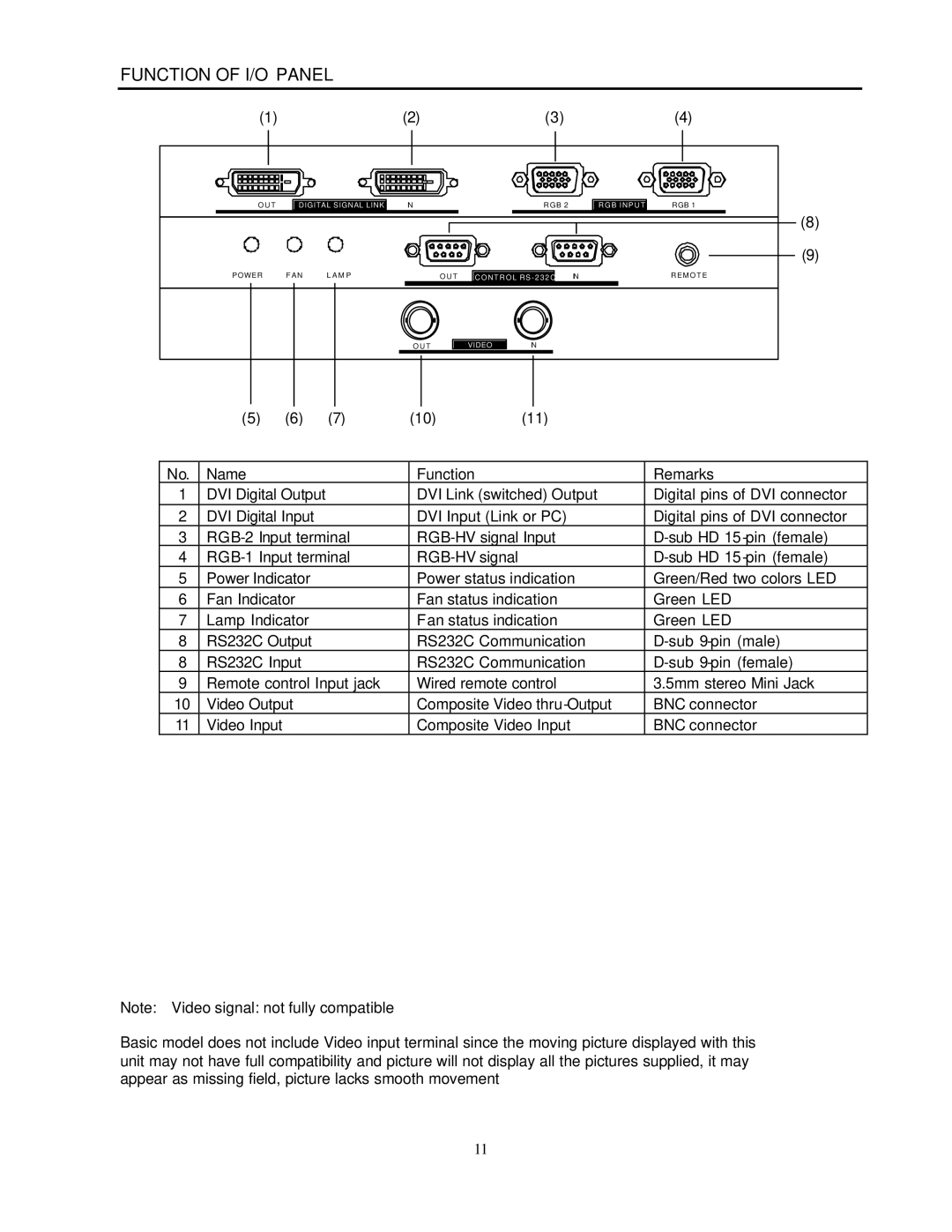
No. | Name |
|
| Function |
| Remarks |
1 | DVI Digital Output |
| DVI Link (switched) Output | Digital pins of DVI connector | ||
2 | DVI Digital Input |
| DVI Input (Link or PC) | Digital pins of DVI connector | ||
3 | ||||||
4 |
| |||||
5 | Power Indicator |
| Power status indication | Green/Red two colors LED | ||
6 | Fan Indicator |
| Fan status indication | Green LED | ||
7 | Lamp Indicator |
| Fan status indication | Green LED | ||
8 | RS232C Output |
| RS232C Communication | |||
8 | RS232C Input |
| RS232C Communication | |||
9 | Remote control Input jack | Wired remote control | 3.5mm stereo Mini Jack | |||
10 | Video Output |
| Composite Video | BNC connector | ||
11 | Video Input |
|
| Composite Video Input | BNC connector | |
Note: Video signal: not fully compatible
Basic model does not include Video input terminal since the moving picture displayed with this unit may not have full compatibility and picture will not display all the pictures supplied, it may appear as missing field, picture lacks smooth movement
11