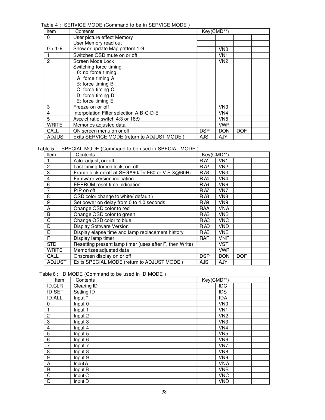
Table 4 : SERVICE MODE (Command to be in SERVICE MODE )
Item | Contents | Key(CMD**) |
0User picture effect Memory User Memory read out
0 | + | Show or update Mag pattern 1 |
|
| VN0 |
|
| |
| 1 |
| Switches OSD mute on or off |
| VN1 |
|
| |
| 2 |
| Screen Mode Lock |
| VN2 |
|
| |
|
|
| Switching force timing |
|
|
|
| |
|
|
| 0: no force timing |
|
|
|
| |
|
|
| A: force timing A |
|
|
|
| |
|
|
| B: force timing B |
|
|
|
| |
|
|
| C: force timing C |
|
|
|
| |
|
|
| D: force timing D |
|
|
|
| |
|
|
| E: force timing E |
|
|
|
| |
| 3 |
| Freeze on or off |
| VN3 |
|
| |
| 4 |
| Interpolation Filter selection |
| VN4 |
|
| |
| 5 |
| Aspe ct ratio switch 4:3 or 16:9 |
| VN5 |
|
| |
| WRITE | Memories adjusted data |
| VWR |
|
| ||
| CALL | ON screen menu on or off | DSP | DON | DOF | |||
| ADJUST | Exits SERVICE MODE (return to ADJUST MODE ) | AJS | AJY |
|
| ||
Table 5 : SPECIAL MODE (Command to be used in SPECIAL MODE ) |
|
|
|
| ||||
| Item | Contents |
| Key(CMD**) |
|
| ||
| 1 |
| Auto |
| R A1 | VN1 |
|
|
| 2 |
| Last timing forced lock, |
| R A2 | VN2 |
|
|
| 3 |
| Frame lock |
| R A3 | VN3 |
|
|
| 4 |
| Firmware version indication |
| R A4 | VN4 |
|
|
| 6 |
| EEPROM reset time indication |
| R A6 | VN6 |
|
|
| 7 |
| PIP |
| R A7 | VN7 |
|
|
| 8 |
| OSD color change to white( default ) |
| R A8 | VN8 |
|
|
| 9 |
| Set power on delay from 0 to 4.0 seconds |
| R A9 | VN9 |
|
|
| A |
| Change OSD color to red |
| RAA | VNA |
|
|
| B |
| Change OSD color to green |
| R AB | VNB |
|
|
| C |
| Change OSD color to blue |
| R AC | VNC |
|
|
| D |
| Display Software Version |
| R AD | VND |
|
|
| E |
| Display elapse time and lamp replacement history |
| R AE | VNE |
|
|
| F |
| Display lamp timer |
| RAF | VNF |
|
|
| STD | Resetting present lamp timer (uses after F, then Write) |
|
| VST |
|
| |
| WRITE | Memorizes adjusted data |
|
| VWR |
|
| |
| CALL | Onscreen display on or off |
| DSP | DON | DOF |
| |
| ADJUST | Exits SPECIAL MODE (return to ADJUST MODE ) |
| AJS | AJY |
|
| |
Table 6 : ID MODE (Command to be used in ID MODE ) |
|
|
|
| ||||
|
| Item | Contents |
| Key(CMD**) |
|
| |
| ID.CLR | Clearing ID |
|
| IDC |
|
| |
| ID.SET | Setting ID |
|
| IDS |
|
| |
| ID.ALL | Input * |
|
| IDA |
|
| |
| 0 |
| Input 0 |
|
| VN0 |
|
|
| 1 |
| Input 1 |
|
| VN1 |
|
|
| 2 |
| Input 2 |
|
| VN2 |
|
|
| 3 |
| Input 3 |
|
| VN3 |
|
|
| 4 |
| Input 4 |
|
| VN4 |
|
|
| 5 |
| Input 5 |
|
| VN5 |
|
|
| 6 |
| Input 6 |
|
| VN6 |
|
|
| 7 |
| Input 7 |
|
| VN7 |
|
|
| 8 |
| Input 8 |
|
| VN8 |
|
|
| 9 |
| Input 9 |
|
| VN9 |
|
|
| A |
| Input A |
|
| VNA |
|
|
| B |
| Input B |
|
| VNB |
|
|
| C |
| Input C |
|
| VNC |
|
|
| D |
| Input D |
|
| VND |
|
|
38