English Français Español Deutsch Italiano Português Svenska
Parts on the rear panel
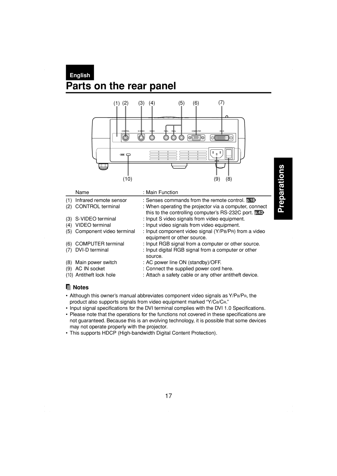
(1) | (2) | (3) | (4) |
| (5) | (6) | (7) | |||||
|
|
|
|
|
|
|
|
|
|
|
|
|
|
|
|
|
|
|
|
|
|
|
|
|
|
|
|
|
|
|
|
|
|
|
|
|
|
|
|
|
|
|
|
|
|
|
|
|
|
|
|
| (10) | (9) | (8) |
| Name | : Main Function |
|
(1) | Infrared remote sensor | : Senses commands from the remote control. p.18 | |
(2) | CONTROL terminal | : When operating the projector via a computer, connect | |
|
| this to the controlling computer’s | |
(3) | : Input S video signals from video equipment. | ||
(4) | VIDEO terminal | : Input video signals from video equipment. | |
(5) | Component video terminal | : Input component video signal (Y/PB/PR) from a video | |
|
| equipment or other source. |
|
(6) | COMPUTER terminal | : Input RGB signal from a computer or other source. | |
(7) | : Input digital RGB signal from a computer or other | ||
|
| source. |
|
(8) | Main power switch | : AC power line ON (standby)/OFF. |
|
(9) | AC IN socket | : Connect the supplied power cord here. | |
(10) | Antitheft lock hole | : Attach a safety cable or any other antitheft device. | |
![]() Notes
Notes
•Although this owner’s manual abbreviates component video signals as Y/PB/PR, the product also supports signals from video equipment marked “Y/CB/CR.”
•Input signal specifications for the DVI terminal complies with the DVI 1.0 Specifications.
•Please note that the operations for the functions not covered in these specifications are not guaranteed. Because this is an evolving technology, it is possible that some devices may not operate properly with the projector.
•This supports HDCP
Preparations
17