Specifications (Continued)
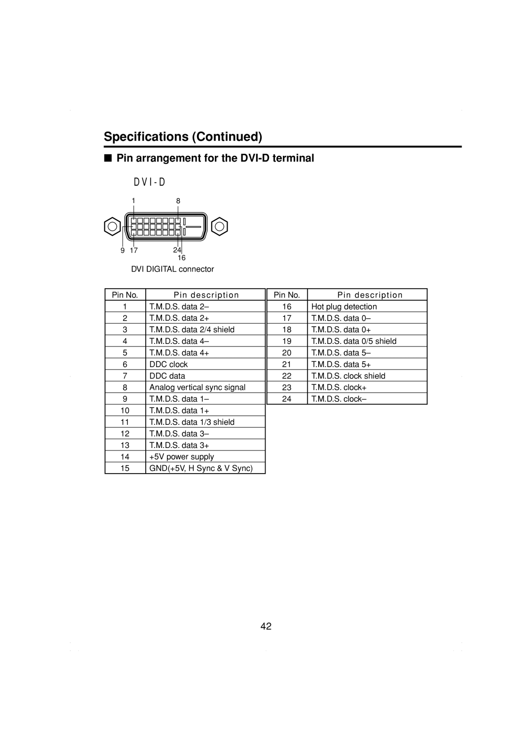
■Pin arrangement for the DVI-D terminal D V I - D
1
8
9 17 24
16
DVI DIGITAL connector
Pin No. | Pin description |
1 | T.M.D.S. data 2– |
2 | T.M.D.S. data 2+ |
3 | T.M.D.S. data 2/4 shield |
4 | T.M.D.S. data 4– |
5 | T.M.D.S. data 4+ |
6 | DDC clock |
7 | DDC data |
8 | Analog vertical sync signal |
9 | T.M.D.S. data 1– |
10 | T.M.D.S. data 1+ |
11 | T.M.D.S. data 1/3 shield |
12 | T.M.D.S. data 3– |
13 | T.M.D.S. data 3+ |
14 | +5V power supply |
15 | GND(+5V, H Sync & V Sync) |
Pin No. | Pin description |
16 | Hot plug detection |
17 | T.M.D.S. data 0– |
18 | T.M.D.S. data 0+ |
19 | T.M.D.S. data 0/5 shield |
20 | T.M.D.S. data 5– |
21 | T.M.D.S. data 5+ |
22 | T.M.D.S. clock shield |
23 | T.M.D.S. clock+ |
24 | T.M.D.S. clock– |
42