Commercial Self-Contained
December
Introduction
Signature Series Self-Contained Units
Contents
Features and Benefits
Standard Features
Optional Features
Integrated Self-Contained Systems
Integrated Comfort System ICS
Low Torque Variation
Proven DesignThroughTesting and Research
Trane 3-DScroll Compressor
Supply Air Ductwork
Application Considerations Self-Contained
Return Air Ductwork
Equipment Room Location and Orientation
Isolation Recommendations
Condenser Water Piping
Unit Operating Limits
Considerations
Application
Air Cooled
Condenser
Unit Capacities
Procedure Self-Contained
Selection
Waterside Economizer Capacity
Selection Example Design Conditions
Unit Selection
Description
Procedure
Model Number
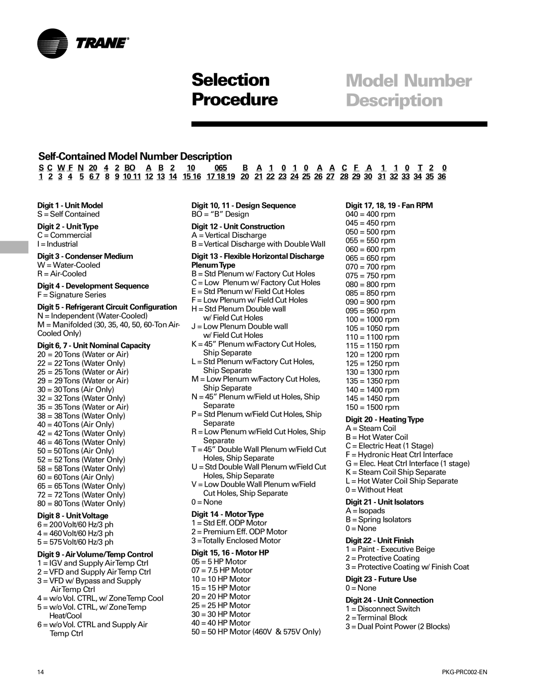
Self-Contained Model Number Description
Self-Contained Accessory Model Number Description
Remote Air-Cooled Condenser Model Number Description
General Data
Tons
Table GD-3. SCWF/SIWF Water-Cooled Self-Contained, 42-80Tons
SCRF/SIRF
Table GD-4. SCRF/SIRF Air-Cooled Self-Contained
General Data
CCRC/CIRC
Heating Coil
Table GD-7. Self-Contained Heating Coil
Drops
Data
Chart PD-5. Airside Pressure Drop
Performance
Drops
Airside Pressure
Heating Coils
Discharge Plenum
20 to 38 Ton Unit 42 to 80 Ton Unit
Airside Pressure
Airside Economizer with Standard Damper
Airside Economizer with Traq Damper
Pressure Drop
Chart PD-21. Waterside Pressure Drop SCWF/SIWF 35
Waterside
SCWF/SIWF
Performance Water-Cooled Data
Table PD-1. CFM Capacity Correction Table
Table PD-2. SCWF/SIWF 20 Economizer Full Capacity 8,000 cfm
Water-Cooled
20 Ton
Table PD-3. SCWF/SIWF 20 Economizer Low Capacity 8,000 cfm
Entering WaterTemp Entering Air 75 F 85 F 95 F
Table PD-6. SCWF/SIWF 22 Economizer Low Capacity 8,800 cfm
22 Ton
Table PD-5. SCWF/SIWF 22 Economizer Full Capacity 8,800 cfm
EnteringWaterTemp Entering Air 75 F 85 F 95 F
25 Ton
Table PD-9. SCWF/SIWF 25 Economizer Low Capacity 10,000 cfm
Entering Water Temp Entering Air 75 F 85 F 95 F
29 Ton
Table PD-12. SCWF/SIWF 29 Economizer Low Capacity 11,600 cfm
84.2
32 Ton
Table PD-15. SCWF/SIWF 32 Economizer Low Capacity 12,800 cfm
94.5
35 Ton
Table PD-18. SCWF/SIWF 35 Economizer Low Capacity 14,000 cfm
401 320
38 Ton
Table PD-21. SCWF/SIWF 38 Economizer Low Capacity 15,200 cfm
434 373
42 Ton
Table PD-24. SCWF/SIWF 42 Economizer Low Capacity 16,800 cfm
403 84.1
46 Ton
Table PD-27. SCWF/SIWF 46 Economizer Low Capacity 18,400 cfm
83.8
52 Ton
Table PD-30. SCWF/SIWF 52 Economizer Low Capacity 20,800 cfm
596 471
58 Ton
Table PD-33. Scwfsiwf 58 Economizer Low Capacity 23,200 cfm
663 571
65 Ton
Table PD-36. SCWF/SIWF 65 Economizer Low Capacity 26,000 cfm
Entering Water Temp Entering Air
72 Ton
Table PD-39. SCWF/SIWF 72 Economizer Low Capacity 28,000 cfm
83.7
80 Ton
Table PD-42. SCWF/SIWF 80 Economizer Low Capacity 29,800 cfm
891 761
Air-Cooled
Table PD-45. SCRF/SIRF 25 Gross Cooling Capacity 11,600 cfm
Table PD-46. SCRF/SIRF 29 Gross Cooling Capacity 12,800 cfm
30 Ton
Table PD-47. SCRF/SIRF 30 Gross Cooling Capacity 14,000 cfm
Table PD-48. SCRF/SIRF 35 Gross Cooling Capacity 15,200 cfm
40 Ton
Table PD-49. SCRF/SIRF 40 Gross Cooling Capacity 18,400 cfm
50 Ton
Table PD-50. SCRF/SIRF 50 Gross Cooling Capacity 23,200 cfm
Table PD-51. SCRF/SIRF 60 Gross Cooling Capacity 29,800 cfm
Performance Air-Cooled
Data60-Ton
Table PD-52. HotWater Heating Capacity
Self-Contained
Heating Coils
Table PD-53. Steam Heating Capacity
Controls
Available Input and Output Points
Human Interface Panel HI
Standard IntelliPak Unit Control Features
IntelliPak Unit Features
Main menus of the human interface panels are
Control Sequences Operation
Sequence
Controls Operation
Gbas Binary Outputs
Generic Building Automation System Module Gbas Option
Gbas Analog Inputs
Demand Limiting Binary Input
Water Purge
Airside Options
Air-Cooled Condensers
Inlet GuideVane Control
Heating Electric
Occupied ZoneTemperature Control
Unoccupied ZoneTemperature Control Cooling and Heating
Heating Hot Water or Steam
Supply Air Tempering Hot Water and Steam Units Only
Supply Air Temperature Control Unit Sequence Operation
Supply Air Setpoint Reset
Standard On All Units
Zone Sensor
Controls Options
Model Number Digit 6 = A, BAYSENS017
Thermometer to indicate temperature in the zone
Setpoint thumbwheel for local setpoint adjustment
Selection Procedures
Electrical Data
Table ED-7. CCRC/CIRC Condenser Electrical Data
Electrical Data SCWF/SCRF
Table ED-6. Single Stage Electric Heat Electrical Data
Dimensions Self-Contained Weights Tons
Ton Self-Contained
Dimensions Self-Contained Weights 40-80 Ton
Discharge Dimensions Metric mm
Detail B Discharge Dimensions
Discharge Dimensions English inches
Detail a Electrical Connections
Dimensions Air-Cooled Weights Condenser
Ccrc Unit Dimensions
Refrigerant and Electrical Connections
Dimensions
Weights
Front View Looking at Control Panel
Hot Water Coil
Steam Coil
Plenum Dimensions Metric mm
Dimensions
Plenum Dimensions English inches
Flexible Horizontal Discharge Plenum
Airside Economizer
Airside
Economizer
Airside Economizer Dimensions English inches
Airside Economizer Dimensions Metric mm
Zone Sensors
Field-Installed
Adjustment
Dual Setpoint, Manual/Automatic
Programmable Night-Setback Sensor
Zone Temperature Sensor Only
Function Lights
Clearances
Service
Service/Code Clearance Requirements
Self-Contained Models
Top View CCRC/CIRC 50
Top View CCRC/CIRC 20
Top View CCRC/CIRC 35
Table W-2. Unit Weights CCRC/CIRC
Dimensions Weights
Table W-1. Unit Weights SCWF/SCRF/SIWF/SIRF
Table W-3. Variable Frequency Drive Weights
Mechanical Specifications Self-Contained
Signature Series Self Contained Units
Mechanical Air-CooledSpecifications Condenser
Supply Air Temperature Control with Inlet GuideVanes
Mechanical Specifications Options
Air Volume/Temperature Control Zone Temperature Control
Self-Contained Options
Airside Economizer Interface
Comparative Enthalpy Control
Standard Two-Position Damper Interface
Airside Economizer Interface with Comparative Enthalpy
Low Entering Air Temperature Protection Device
Water Flow Switch
Service Valves
Non-fused Disconnect Switch
Cupro-Nickel Condenser
Protective Coating Cabinet
Coils
Stainless Steel Drain Pan
Literature Order Number