ASSEMBLY INSTRUCTIONS
TOOLS REQUIRED
9⁄16˝ Wrench • 1⁄2˝ Wrench • Phillips Screwdriver • 3⁄16˝ Hex Key (provided)
LOCATE THE HARDWARE BAG SA2023 CONTAINING:
Part # | Description. | Qty. |
HH2102 | Button Head Bolt 5/16” X 1” | 8 |
MM2105 | Nylon Shoulder Washer | 4 |
HH2168 | Hex Head Bolt 5/16” X 1 1/2” | 2 |
HH2154 | Black Flat Washer | 12 |
HH2095 | 3/8 Star Washer | 4 |
HH2153 | Hex Head Bolt 5/16” X 5” | 2 |
HH2001 | Hex Key Wrench | 1 |
MM0087 | Hex Key Clip | 1 |
HH2217 | Phillips Head screw | 7 |
CAUTION: DO NOT PLUG IN POWER CORD UNTIL
FINAL ASSEMBLY IS COMPLETE AND MOTOR COVER IS INSTALLED.
STEP 1
Remove contents from box: (1) upright assembly, (2) handrails, (1) hardware bag, (1) main base.
STEP 2
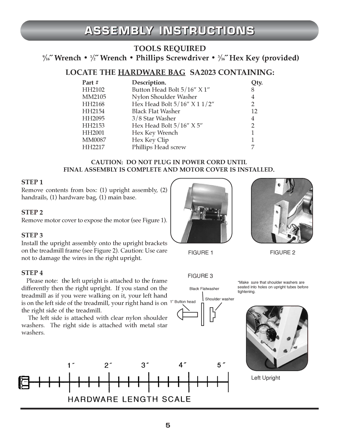
Remove motor cover to expose the motor (see Figure 1).
STEP 3
Install the upright assembly onto the upright brackets on the treadmill frame (see Figure 2). Caution: Use care not to damage the wires in the right upright.
STEP 4
Please note: the left upright is attached to the frame differently then the right upright. If you stand on the treadmill as if you were walking on it, your left hand
FIGURE 1
FIGURE 3
Black Flatwasher
FIGURE 2
*Make sure that shoulder washers are seated into holes on upright tubes before tightening.
is on the left side of the treadmill, your right hand is on the right side of the treadmill.
The left side is attached with clear nylon shoulder washers. The right side is attached with metal star washers.
1” Button head
Shoulder washer
Left Upright
5