SRCOOL33K, SRXCOOL33K specifications
The Tripp Lite SRXCOOL33K is a premier portable air conditioning unit designed specifically for cooling server rooms, data centers, and other critical environments where temperature control is paramount. With its effective cooling capabilities and user-friendly design, this unit is an essential tool for IT professionals seeking reliable temperature management solutions.One of the primary features of the SRXCOOL33K is its impressive cooling capacity. With a powerful output of 33,000 BTUs, it can efficiently cool spaces up to 1,000 square feet, making it ideal for larger rooms or areas with a high concentration of heat-generating equipment. This capacity is particularly critical in maintaining optimal operating conditions for servers and networking equipment, which can be adversely affected by elevated temperatures.
In addition to its cooling prowess, the SRXCOOL33K incorporates advanced technologies that enhance its performance. The unit utilizes a high-efficiency rotary compressor, which not only improves cooling efficiency but also reduces energy consumption. This energy-efficient design can lead to significant cost savings on utility bills, making it a smart investment for any organization.
The SRXCOOL33K also features a host of user-friendly characteristics, making it straightforward to operate and maintain. The digital control panel allows users to set and monitor temperatures with precision, while the included remote control adds convenience for adjusting settings from a distance. Furthermore, the unit is equipped with a programmable timer, enabling scheduled operation to match peak cooling needs.
Portability is another standout feature of the SRXCOOL33K. With easy-rolling casters and side handles, it can be effortlessly moved to different locations as required. This flexibility is particularly advantageous for organizations that may need to reposition their cooling solutions in response to varying equipment loads or spatial configurations.
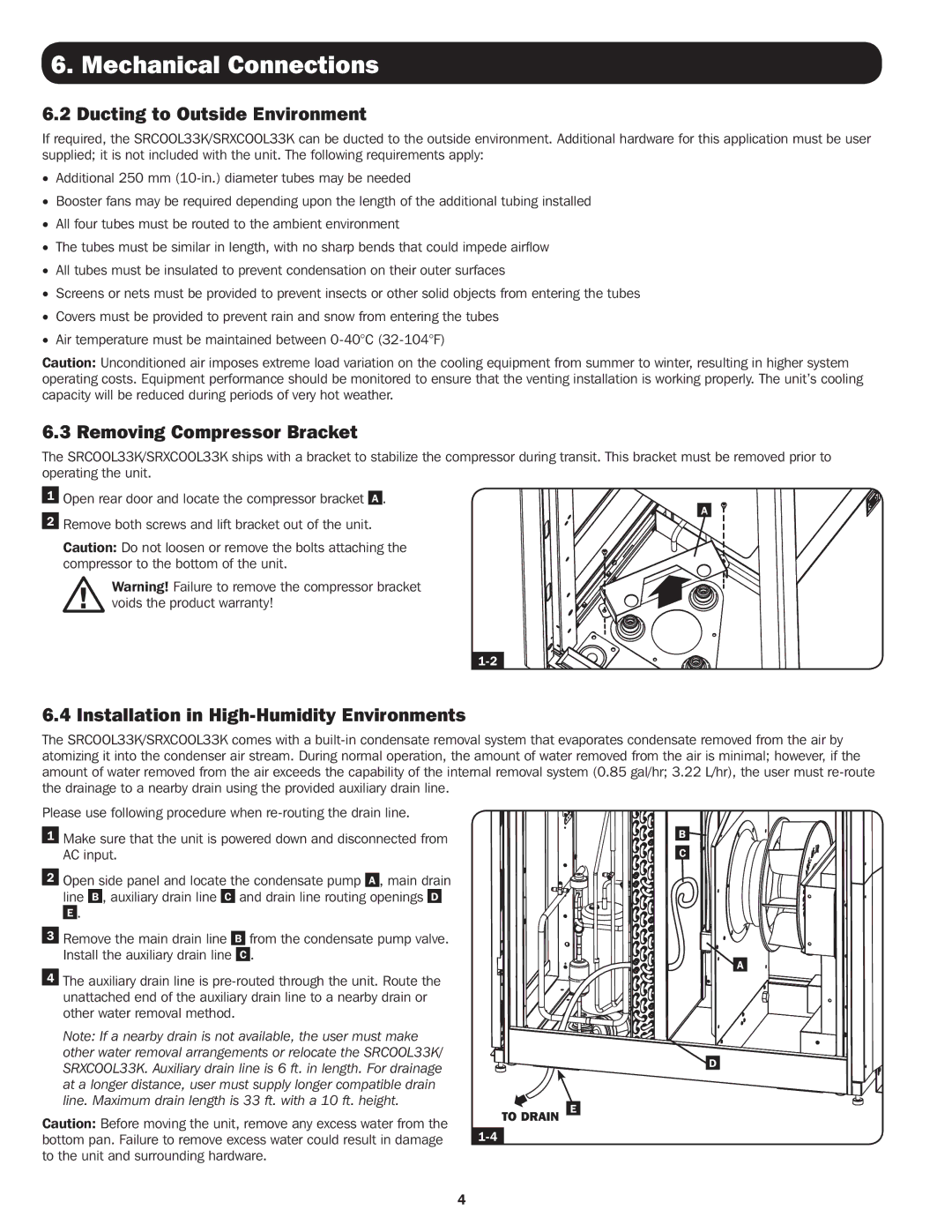
The air conditioner also includes a built-in condensate pump that automatically removes water collected during operation, eliminating the need for manual drainage. This adds to its low-maintenance nature, allowing IT staff to focus on their core tasks without the hassle of frequent upkeep.
In conclusion, the Tripp Lite SRXCOOL33K stands out as a robust and versatile cooling solution for professionals in the IT and data management sectors. With its exceptional cooling capacity, energy-efficient technologies, and portability, it effectively supports maintaining the ideal conditions for critical equipment.

