Tripp Lite SU6000RT4U Rear Panel Features Power/Battery Module and Detachable PDU Together

Models: SU5000RT4U SU6000RT4U SU8000RT4U

1 52
Download 52 pages 59.76 Kb
Page 4
Image 4
Rear Panel Features (Power/Battery Module and Detachable PDU Together)

Features (continued)

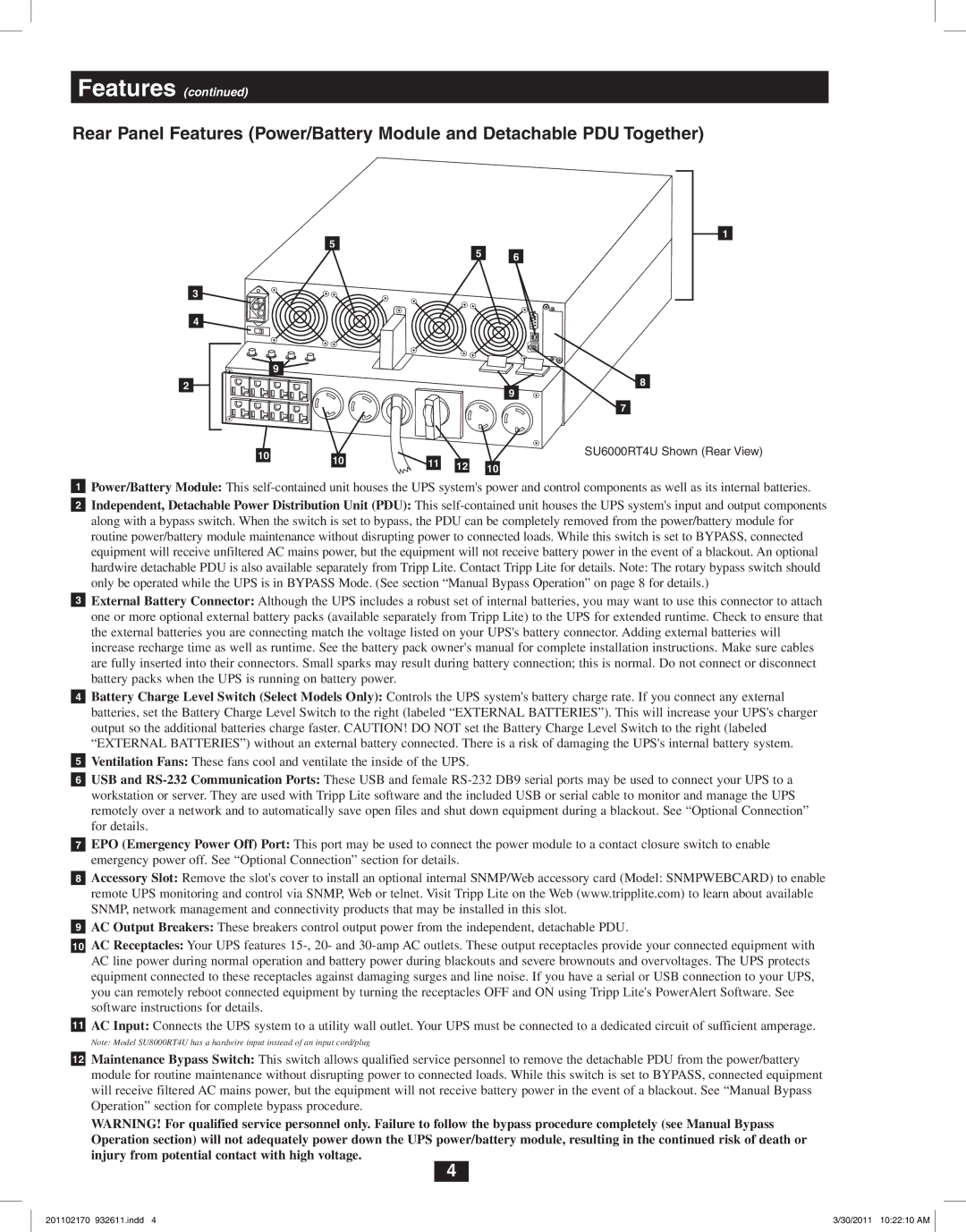
Rear Panel Features (Power/Battery Module and Detachable PDU Together)

5

9 Manual background

5 6

8

9

7

10

10

11


SU6000RT4U Shown (Rear View)

12


10


Manual background Power/Battery Module: This self-contained unit houses the UPS system's power and control components as well as its internal batteries.

Manual background Independent, Detachable Power Distribution Unit (PDU): This self-contained unit houses the UPS system's input and output components along with a bypass switch. When the switch is set to bypass, the PDU can be completely removed from the power/battery module for routine power/battery module maintenance without disrupting power to connected loads. While this switch is set to BYPASS, connected equipment will receive unfiltered AC mains power, but the equipment will not receive battery power in the event of a blackout. An optional hardwire detachable PDU is also available separately from Tripp Lite. Contact Tripp Lite for details. Note: The rotary bypass switch should only be operated while the UPS is in BYPASS Mode. (See section “Manual Bypass Operation” on page 8 for details.)

Manual background External Battery Connector: Although the UPS includes a robust set of internal batteries, you may want to use this connector to attach one or more optional external battery packs (available separately from Tripp Lite) to the UPS for extended runtime. Check to ensure that the external batteries you are connecting match the voltage listed on your UPS's battery connector. Adding external batteries will increase recharge time as well as runtime. See the battery pack owner's manual for complete installation instructions. Make sure cables are fully inserted into their connectors. Small sparks may result during battery connection; this is normal. Do not connect or disconnect battery packs when the UPS is running on battery power.

Manual background Battery Charge Level Switch (Select Models Only): Controls the UPS system's battery charge rate. If you connect any external batteries, set the Battery Charge Level Switch to the right (labeled “EXTERNAL BATTERIES”). This will increase your UPS's charger output so the additional batteries charge faster. CAUTION! DO NOT set the Battery Charge Level Switch to the right (labeled “EXTERNAL BATTERIES”) without an external battery connected. There is a risk of damaging the UPS's internal battery system.

Manual background Ventilation Fans: These fans cool and ventilate the inside of the UPS.

Manual background USB and RS-232 Communication Ports: These USB and female RS-232 DB9 serial ports may be used to connect your UPS to a workstation or server. They are used with Tripp Lite software and the included USB or serial cable to monitor and manage the UPS remotely over a network and to automatically save open files and shut down equipment during a blackout. See “Optional Connection” for details.

Manual background EPO (Emergency Power Off) Port: This port may be used to connect the power module to a contact closure switch to enable emergency power off. See “Optional Connection” section for details.

Manual background Accessory Slot: Remove the slot's cover to install an optional internal SNMP/Web accessory card (Model: SNMPWEBCARD) to enable remote UPS monitoring and control via SNMP, Web or telnet. Visit Tripp Lite on the Web (www.tripplite.com) to learn about available SNMP, network management and connectivity products that may be installed in this slot.

Manual background AC Output Breakers: These breakers control output power from the independent, detachable PDU.

Manual background AC Receptacles: Your UPS features 15-, 20- and 30-amp AC outlets. These output receptacles provide your connected equipment with AC line power during normal operation and battery power during blackouts and severe brownouts and overvoltages. The UPS protects equipment connected to these receptacles against damaging surges and line noise. If you have a serial or USB connection to your UPS, you can remotely reboot connected equipment by turning the receptacles OFF and ON using Tripp Lite's PowerAlert Software. See software instructions for details.

Manual background AC Input: Connects the UPS system to a utility wall outlet. Your UPS must be connected to a dedicated circuit of sufficient amperage.

Note: Model SU8000RT4U has a hardwire input instead of an input cord/plug

Manual background Maintenance Bypass Switch: This switch allows qualified service personnel to remove the detachable PDU from the power/battery module for routine maintenance without disrupting power to connected loads. While this switch is set to BYPASS, connected equipment will receive filtered AC mains power, but the equipment will not receive battery power in the event of a blackout. See “Manual Bypass Operation” section for complete bypass procedure.

WARNING! For qualified service personnel only. Failure to follow the bypass procedure completely (see Manual Bypass Operation section) will not adequately power down the UPS power/battery module, resulting in the continued risk of death or injury from potential contact with high voltage.

4

201102170 932611.indd 4

3/30/2011 10:22:10 AM

Page 4
Image 4
Tripp Lite SU6000RT4U, SU8000RT4U, SU5000RT4U Rear Panel Features Power/Battery Module and Detachable PDU Together