Section 3: Features and Controls
Verify Position of Clutch Roller
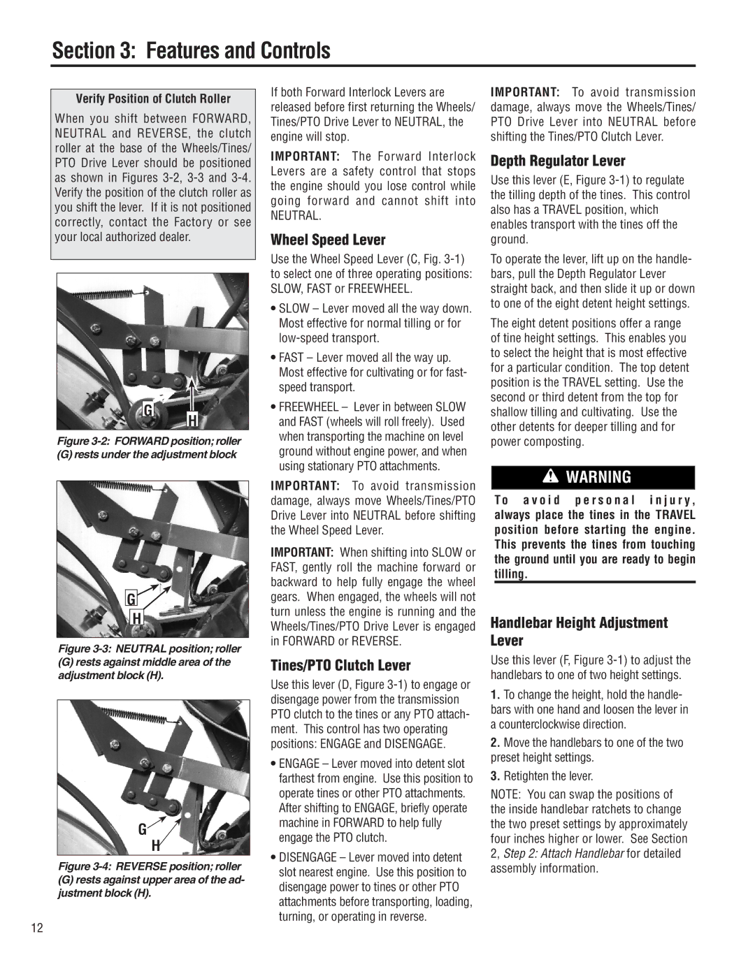
When you shift between FORWARD, NEUTRAL and REVERSE, the clutch roller at the base of the Wheels/Tines/ PTO Drive Lever should be positioned as shown in Figures
G H
Figure 3-2: FORWARD position; roller
(G) rests under the adjustment block
G![]()
H
Figure 3-3: NEUTRAL position; roller
(G)rests against middle area of the adjustment block (H).
G![]()
H
Figure 3-4: REVERSE position; roller
(G)rests against upper area of the ad- justment block (H).
12
If both Forward Interlock Levers are released before first returning the Wheels/ Tines/PTO Drive Lever to NEUTRAL, the engine will stop.
IMPORTANT: The Forward Interlock Levers are a safety control that stops the engine should you lose control while going forward and cannot shift into
NEUTRAL.
Wheel Speed Lever
Use the Wheel Speed Lever (C, Fig.
•SLOW – Lever moved all the way down. Most effective for normal tilling or for
•FAST – Lever moved all the way up. Most effective for cultivating or for fast- speed transport.
•FREEWHEEL – Lever in between SLOW and FAST (wheels will roll freely). Used when transporting the machine on level ground without engine power, and when using stationary PTO attachments.
IMPORTANT: To avoid transmission damage, always move Wheels/Tines/PTO Drive Lever into NEUTRAL before shifting the Wheel Speed Lever.
IMPORTANT: When shifting into SLOW or FAST, gently roll the machine forward or backward to help fully engage the wheel gears. When engaged, the wheels will not turn unless the engine is running and the Wheels/Tines/PTO Drive Lever is engaged in FORWARD or REVERSE.
Tines/PTO Clutch Lever
Use this lever (D, Figure
•ENGAGE – Lever moved into detent slot farthest from engine. Use this position to operate tines or other PTO attachments. After shifting to ENGAGE, briefly operate machine in FORWARD to help fully engage the PTO clutch.
•DISENGAGE – Lever moved into detent slot nearest engine. Use this position to disengage power to tines or other PTO attachments before transporting, loading, turning, or operating in reverse.
IMPORTANT: To avoid transmission damage, always move the Wheels/Tines/ PTO Drive Lever into NEUTRAL before shifting the Tines/PTO Clutch Lever.
Depth Regulator Lever
Use this lever (E, Figure
To operate the lever, lift up on the handle- bars, pull the Depth Regulator Lever straight back, and then slide it up or down to one of the eight detent height settings.
The eight detent positions offer a range of tine height settings. This enables you to select the height that is most effective for a particular condition. The top detent position is the TRAVEL setting. Use the second or third detent from the top for shallow tilling and cultivating. Use the other detents for deeper tilling and for power composting.
![]() WARNING
WARNING
To a v o i d p e r s o n a l i n j u r y , always place the tines in the TRAVEL position before starting the engine. This prevents the tines from touching the ground until you are ready to begin tilling.
Handlebar Height Adjustment Lever
Use this lever (F, Figure
1.To change the height, hold the handle- bars with one hand and loosen the lever in a counterclockwise direction.
2.Move the handlebars to one of the two preset height settings.
3.Retighten the lever.
NOTE: You can swap the positions of the inside handlebar ratchets to change the two preset settings by approximately four inches higher or lower. See Section 2, Step 2: Attach Handlebar for detailed assembly information.