Section 4: Operation
Figure 4-24: Loosening attachment swing-bolts.
10.The PTO Power Unit is now ready to install other powered or
Installing the Tine Attachment
1.Move the two PTO Power Unit swing- out bolts outward and slide the washers up against the bolt heads.
2.Remove the support block from under the engine and slowly roll the power unit back next to the tine attachment. Place the support block back under the engine.
3.Remove the dust cap (or protective wrapping) from the dog clutch coupling on the tine attachment.
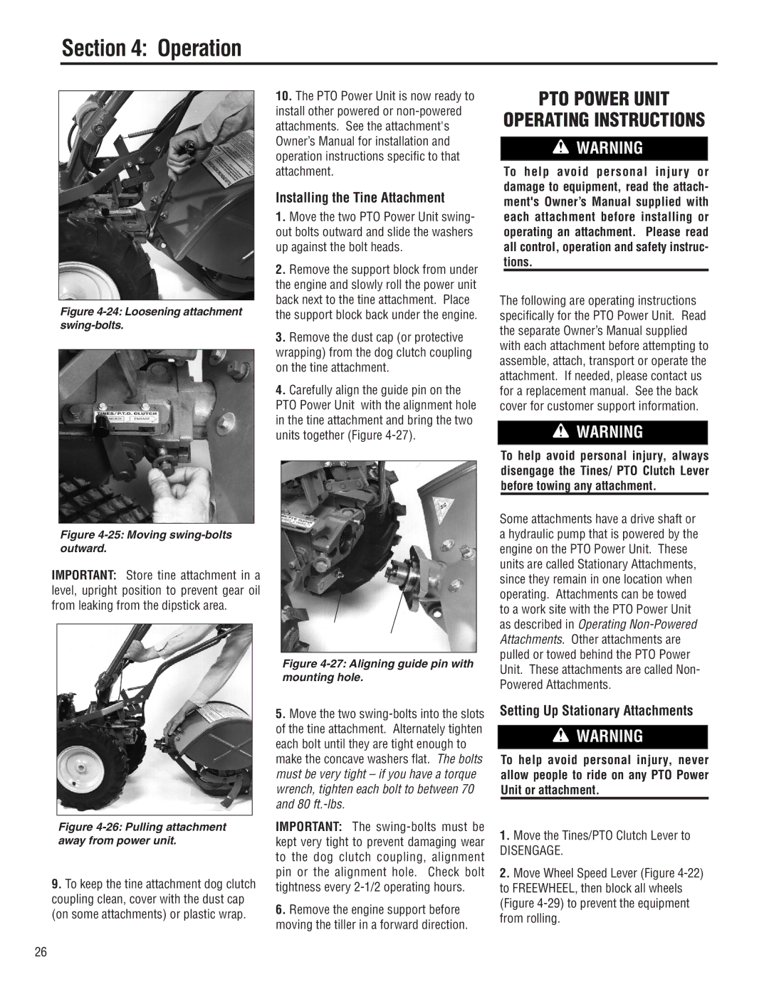
4.Carefully align the guide pin on the PTO Power Unit with the alignment hole in the tine attachment and bring the two units together (Figure
PTO POWER UNIT
OPERATING INSTRUCTIONS
![]() WARNING
WARNING
To help avoid personal injury or damage to equipment, read the attach- ment's Owner’s Manual supplied with each attachment before installing or operating an attachment. Please read all control, operation and safety instruc- tions.
The following are operating instructions specifically for the PTO Power Unit. Read the separate Owner’s Manual supplied with each attachment before attempting to assemble, attach, transport or operate the attachment. If needed, please contact us for a replacement manual. See the back cover for customer support information.
![]() WARNING
WARNING
To help avoid personal injury, always disengage the Tines/ PTO Clutch Lever before towing any attachment.
Figure 4-25: Moving swing-bolts outward.
IMPORTANT: Store tine attachment in a level, upright position to prevent gear oil from leaking from the dipstick area.
Some attachments have a drive shaft or a hydraulic pump that is powered by the engine on the PTO Power Unit. These units are called Stationary Attachments, since they remain in one location when operating. Attachments can be towed to a work site with the PTO Power Unit as described in Operating
Figure 4-26: Pulling attachment away from power unit.
9.To keep the tine attachment dog clutch coupling clean, cover with the dust cap (on some attachments) or plastic wrap.
Figure 4-27: Aligning guide pin with mounting hole.
5.Move the two
IMPORTANT: The
6.Remove the engine support before moving the tiller in a forward direction.
Unit. These attachments are called Non- Powered Attachments.
Setting Up Stationary Attachments
![]() WARNING
WARNING
To help avoid personal injury, never allow people to ride on any PTO Power Unit or attachment.
1.Move the Tines/PTO Clutch Lever to
DISENGAGE.
2.Move Wheel Speed Lever (Figure
26