10
INSTALLATION
INSTALLATION
Continued
BUILT-IN FIREPLACE INSTALLATION
| Actual |
|
| Framing | ||||
|
|
|
|
| ||||
Height | 32 3/8" |
|
| 33" | ||||
Front Width | 34 | 5/ | 16 | " |
| 35 | 1/ " | |
|
|
|
|
|
| 2 | ||
Depth | 16 | 11/ | 16 | " | 17 | 3/ " | ||
|
|
|
|
|
| 4 | ||
1.Frame in rough opening. Use dimensions shown in Figure 13 for the rough opening.
If installing in a corner, use dimensions shown in Figure 14, page 10 for the rough opening. The height is 33" which is the same as the wall opening above.
2.If using blower, install and properly ground GA3555, three- prong 120 volt electrical outlet, in fireplace. Follow instruc- tions included in kit.
3.Install gas piping into fireplace location. This installation in- cludes an approved flexible gas line (if allowed by local codes) after the equipment shutoff valve. The flexible gas line must be the last item installed on the gas piping. See Installing Gas Piping to Fireplace Location, page 11.
4.Carefully set fireplace in front of rough opening with back of fireplace inside wall opening.
17 3/4"
33"
![]()
![]() 35 1/2"
35 1/2" ![]()
Figure 13 - Rough Opening for Installing in Wall
39 3/8"
27 7/8"
![]() 35 1/2"
35 1/2" ![]() 55 5/8"
55 5/8"
Figure 14 - Rough Opening for Installing in Corner
5.Plug electrical cord into electrical outlet installed in step 2.
6.Carefully insert fireplace into rough opening.
7.Attach flexible gas line to gas supply. See Connecting Fire- place to Gas Supply, page 12.
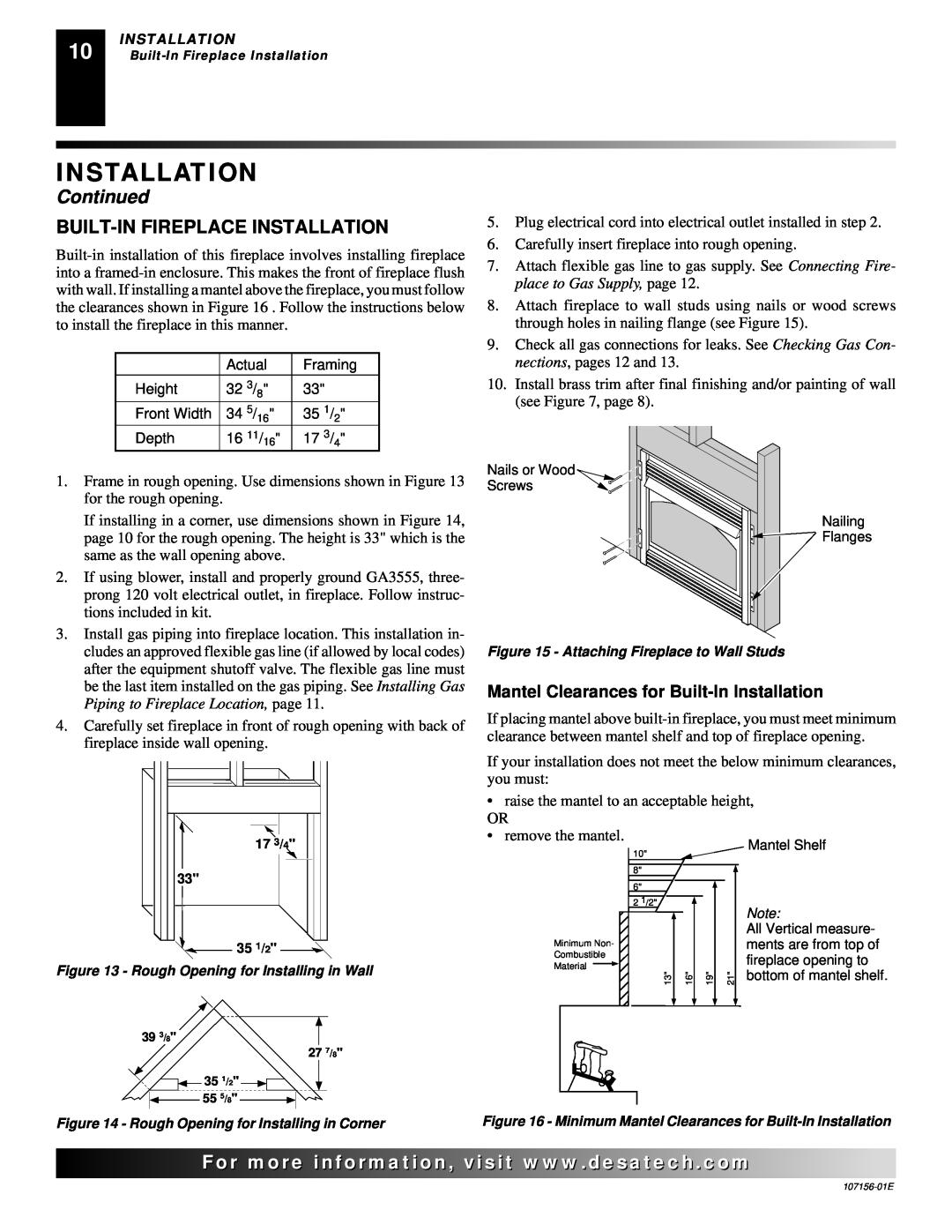
8.Attach fireplace to wall studs using nails or wood screws through holes in nailing flange (see Figure 15).
9.Check all gas connections for leaks. See Checking Gas Con- nections, pages 12 and 13.
10.Install brass trim after final finishing and/or painting of wall (see Figure 7, page 8).
Nails or Wood ![]()
Screws
Nailing
![]()
![]() Flanges
Flanges
Figure 15 - Attaching Fireplace to Wall Studs
Mantel Clearances for Built-In Installation
If placing mantel above
If your installation does not meet the below minimum clearances, you must:
• raise the mantel to an acceptable height,
OR
• remove the mantel.
Mantel Shelf
10" |
|
|
|
|
8" |
|
|
|
|
|
|
|
| |
6" |
|
|
|
|
|
|
|
| |
2 1/2" |
|
|
| Note: |
|
|
| ||
|
|
|
| |
|
|
|
| All Vertical measure- |
Minimum Non- |
|
|
| ments are from top of |
Combustible |
|
|
| fireplace opening to |
Material |
|
|
| |
|
|
| bottom of mantel shelf. | |
13" | 16" | 19" | 21" | |
|
|
|
|
|
Figure 16 - Minimum Mantel Clearances for
![]()
![]()
![]()
![]()
![]() For
For![]()
![]()
![]()
![]()
![]()
![]()
![]()
![]()
![]()
![]()
![]()
![]()
![]() .
.![]()
![]()
![]()
![]() .com
.com![]()
![]()
![]()
![]()
![]()