Radiance Direct Vent /Natural Vent Gas Heater
Assembly Procedures
WARNING
Failure to position the parts in accor- dance with these diagrams or failure to
use only parts specifically approved for use with this heater may result in property dam- age or personal injury.
This heater and components are heavy. Have help available for assembly.
Tools Required
• | Phillips screwdriver (stub) | • | power drill |
• | utility knife | • | reciprocating saw |
• | metal drill bit: size 28 (.140”/3.5mm) | ||
Parts Bag Contents:
•Control door handle/screw
•(3) Vent Screws
•(2) Switch bracket screws
•Ceramic handle w/insert lifter (handle for operable door)
•
(3)Phillips
•(2) Bag of Lava Rocks
•(1) Tube of Vent Gasket Cement
•(1) Vent Restrictor Plate, 2¹⁄₄" inside diameter
•Owner Registration Card
•(4) CS, Hex Hd
•(4) Washer, Fl
Unpack and Assemble Legs
The Radiance is shipped upright. Cut the shipping straps and set stove upright.
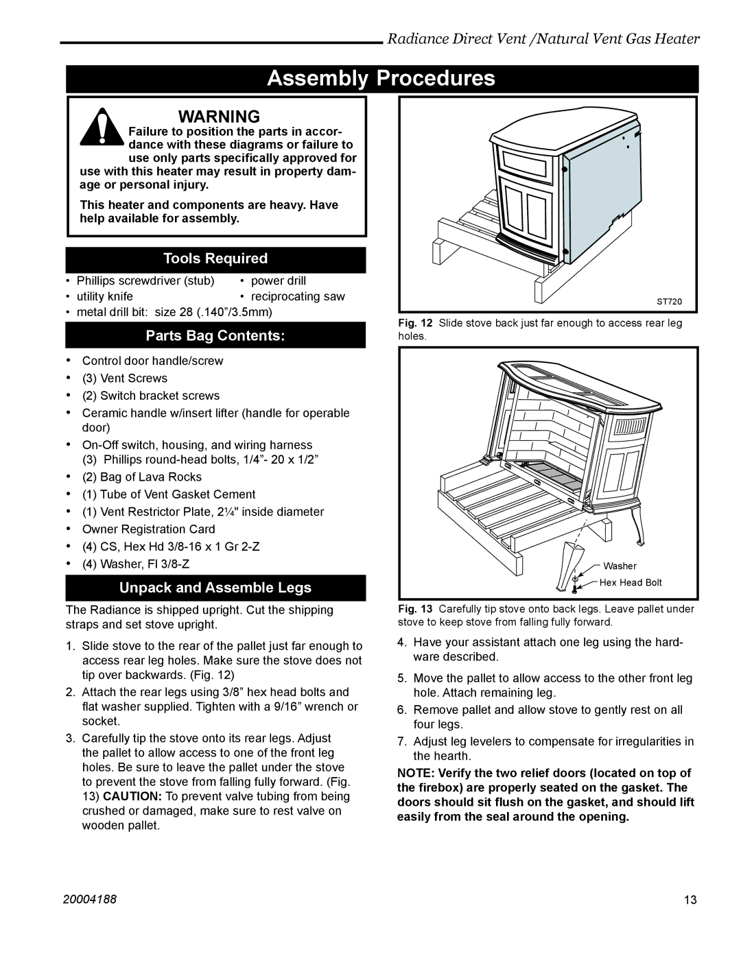
1.Slide stove to the rear of the pallet just far enough to access rear leg holes. Make sure the stove does not tip over backwards. (Fig. 12)
2.Attach the rear legs using 3/8” hex head bolts and flat washer supplied. Tighten with a 9/16” wrench or socket.
3.Carefully tip the stove onto its rear legs. Adjust the pallet to allow access to one of the front leg holes. Be sure to leave the pallet under the stove to prevent the stove from falling fully forward. (Fig. 13) CAUTION: To prevent valve tubing from being crushed or damaged, make sure to rest valve on wooden pallet.
ST720
Fig. 12 Slide stove back just far enough to access rear leg holes.
![]() Washer
Washer
Hex Head Bolt |
Fig. 13 Carefully tip stove onto back legs. Leave pallet under stove to keep stove from falling fully forward.
4.Have your assistant attach one leg using the hard- ware described.
5.Move the pallet to allow access to the other front leg hole. Attach remaining leg.
6.Remove pallet and allow stove to gently rest on all four legs.
7.Adjust leg levelers to compensate for irregularities in the hearth.
NOTE: Verify the two relief doors (located on top of the firebox) are properly seated on the gasket. The doors should sit flush on the gasket, and should lift easily from the seal around the opening.
20004188 | 13 |