Radiance Direct Vent/Natural Vent Gas Heater
WARNING
This appliance is equipped with a
Install the Optional Fan
If you are installing the optional convection Fan Kit #2767 (FK26), continue here. It is easiest to install fan kit before connecting gas line. If you are not installing a Fan Kit, go to Page 15, Venting System Assembly.
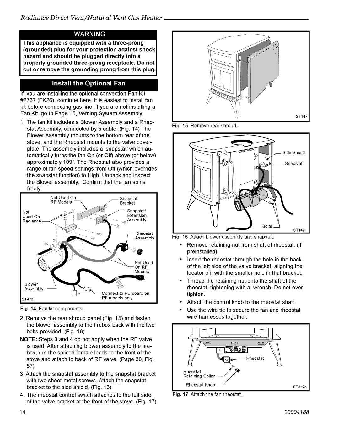
1.The fan kit includes a Blower Assembly and a Rheo- stat Assembly, connected by a cable. (Fig. 14) The Blower Assembly mounts to the bottom rear of the stove, and the Rheostat mounts to the valve cover- plate. The assembly includes a ‘snapstat’ which au- tomatically turns the fan On (or Off) above (or below) approximately 109˚. The Rheostat also provides a range of fan speed settings from Off (which overrides the snapstat function) to High. Unpack and inspect the Blower assembly. Confirm that the fan spins freely.
| Not Used On | Snapstat | |
| RF Models | Bracket | |
Not |
| Snapstat/ | |
| Extension | ||
Used On | |||
Assembly | |||
Radiance | |||
| |||
|
| Rheostat | |
|
| Assembly | |
|
| Not Used | |
|
| On RF | |
|
| Models | |
Blower |
|
| |
Assembly | Connect to PC board on | ||
|
| ||
ST473 |
| RF models only | |
|
| ||
Fig. 14 | Fan kit components. |
| |
2.Remove the rear shroud panel (Fig. 15) and fasten the blower assembly to the firebox back with the two bolts provided. (Fig. 16)
NOTE: Steps 3 and 4 do not apply when the RF valve is used. After attaching blower assembly to the fire- box, run the spliced female leads to the front of the stove and attach to back of RF valve. (Page 30, Fig. 57)
3.Attach the snapstat assembly to the snapstat bracket with two
4.The rheostat control switch attaches to the left side of the valve bracket at the front of the stove. (Fig. 17)
ST147
Fig. 15 Remove rear shroud.
Side Shield
Snapstat |
Bolts
ST149
Fig. 16 Attach blower assembly and snapstat.
•Remove retaining nut from shaft of rheostat. (if preinstalled)
•Insert the rheostat through the hole in the back of the left side of the valve bracket, aligning the locator pin with the smaller hole in that bracket.
•Thread the retaining nut onto the shaft of the rheostat, tightening with a wrench. Do not over- tighten.
•Attach the control knob to the rheostat shaft.
•Use the wire tie to secure the fan and rheostat wire harnesses together.
![]()
![]()
![]()
![]() Rheostat
Rheostat
Rheostat
Retaining Collar
Rheostat Knob | ST347a |
|
Fig. 17 Attach the fan rheostat.
1414 | 20004188 |