Make certain the vent system conforms to all other requirements for vertical termination as specified on Page 9.
This installation will require you to first determine the roof pitch and use the appropriate vent components. Refer to Figure 9 on page 9.
1.Locate the final position of the stove, observing all clearances for both the vent and the stove.
2.Plumb to the center of the inner (4”) flue collar from the ceiling above, and mark that location.
3.Cut the opening:
CFM System: 9³⁄₈” x 9³⁄₈” (240 x 240 mm)
DuraVent System: 10” x 10” (254 x 254 mm)
4.Plumb any additional opening through the roof or other construction that may be needed. In all cases, the opening must provide a minimum of 1” (25 mm) clearance to the vent pipe.
5.Place the stove in its final position.
6.Install firestop(s) #7DVFS and Attic Insulation Shield #7DVAIS as needed. (Fig. 32) If there is a room above ceiling level, a firestop must be installed on both the bottom and top sides of the ceiling joists.
If an attic is above ceiling level, an attic insulation shield must be installed.
#7DVAIS Attic Insulation Shield
Use Four | #7DVFS | |
Firestop in | ||
8d Nails | ||
Upper Floor | ||
|
| #7DVFS | |
ST222 | Firestop in | |
Ceiling | ||
|
Fig. 32 Install firestops and attic insulation shield.
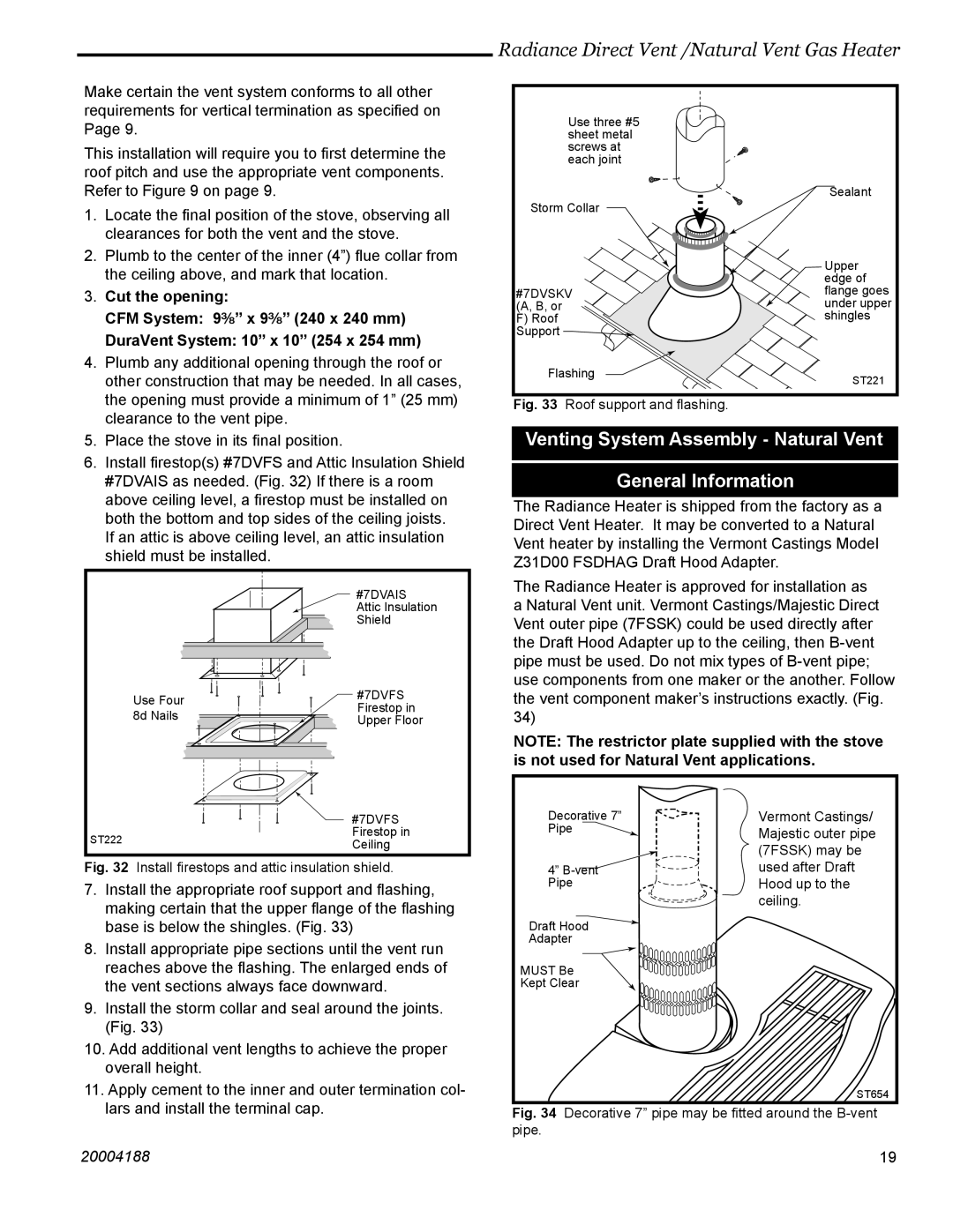
7.Install the appropriate roof support and flashing, making certain that the upper flange of the flashing base is below the shingles. (Fig. 33)
8.Install appropriate pipe sections until the vent run reaches above the flashing. The enlarged ends of the vent sections always face downward.
9.Install the storm collar and seal around the joints. (Fig. 33)
10.Add additional vent lengths to achieve the proper overall height.
11.Apply cement to the inner and outer termination col- lars and install the terminal cap.
Radiance Direct Vent /Natural Vent Gas Heater
| Use three #5 |
|
| sheet metal |
|
| screws at |
|
| each joint |
|
|
| Sealant |
Storm Collar |
| |
|
| Upper |
|
| edge of |
#7DVSKV | flange goes | |
(A, B, or |
| under upper |
F) Roof |
| shingles |
Support |
|
|
Flashing | ST221 | |
|
| |
Fig. 33 | Roof support and flashing. |
|
Venting System Assembly - Natural Vent
General Information
The Radiance Heater is shipped from the factory as a Direct Vent Heater. It may be converted to a Natural Vent heater by installing the Vermont Castings Model Z31D00 FSDHAG Draft Hood Adapter.
The Radiance Heater is approved for installation as a Natural Vent unit. Vermont Castings/Majestic Direct Vent outer pipe (7FSSK) could be used directly after the Draft Hood Adapter up to the ceiling, then
NOTE: The restrictor plate supplied with the stove is not used for Natural Vent applications.
Decorative 7” | Vermont Castings/ |
Pipe | Majestic outer pipe |
| |
| (7FSSK) may be |
4” | used after Draft |
Pipe | Hood up to the |
| ceiling. |
Draft Hood |
|
Adapter |
|
MUST Be |
|
Kept Clear |
|
| ST654 |
Fig. 34 Decorative 7” pipe may be fitted around the B-vent pipe.
20004188 | 19 |