ance when finishing walls above sides of the appli- ance with glass windows. Attach the wall finishing to the constructed frame not the appliance.
5. On DVRTSB models, drywall, wood or wood molding
may be placed with zero clearance to the rear wall of the unit, along the vertical edge formed
by the standoffs to intersection of the rear wall to the side wall containing the small glass window. Attach the wall finishing to the constructed frame, not the appliance.
Final Finishing
Noncombustible materials such as brick or tile may be extended over the edges of the face of the appliance. DO NOT cover any vent or grille panels.
If a Trim Kit is going to be installed on the fireplace, the brick or tile will have to be installed flush with the edges of the appliance.
Gas Specifications
|
|
| Max. | Min. |
|
|
| Input | Input |
Model | Fuel | Gas Control | BTU/h | BTU/h |
DVRTSB RN | Nat | Millivolt | 30,000 | 21,000 |
DVRTSB RP | Prop | Millivolt | 30,000 | 22,500 |
Gas Inlet and Manifold Pressures
| Natural | LP (Propane) |
Inlet Minimum Pressure | 5.5” w.c. | 11.0” w.c. |
Inlet Maximum Pressure | 14.0” w.c. | 14.0” w.c. |
Manifold Pressure | 3.5” w.c. | 10.0” w.c. |
High Elevations
Input ratings are shown in BTU per hour and are certified without deration for elevations up to 4,500 feet (1,370m) above sea level.
For elevations above 4,500 feet (1,370m) in USA, installations must be in accordance with the current ANSI Z223.1/NFPA 54 and/or local codes having jurisdiction.
In Canada, please consult provincial and/or local authorities having jurisdiction for installations at elevations above 4,500 feet (1,370m).
DVRTSB
Certified To
ANSI Z21.88 - 2005 / CSA 2.33 - 2005
Vented Gas Fireplace Heaters
Units: B02A01, B02B01
DVRTSB Bay Window Fireplace
Gas Line Installation
When purging the gas lines, the front glass must be removed.
The gas pipeline can be brought in through the side and back of the fireplace as well as the bottom. Knockouts are provided on the bottom behind the valve to allow for the gas pipe installation and testing of any gas connec- tion. It is most convenient to bring the gas line in from the right side of the valve as this allows fan installation or removal without disconnecting the gas line.
The gas line connection can be made with properly tinned 3/8” copper tubing, 3/8” rigid pipe or an approved flex connector. Since some municipalities have addi- tional local codes, it is always best to consult your local authority and the
For USA installations consult the current National Fuel Gas Code, ANSI Z223.1/NFPA 54.
Always check for gas leaks with a mild soap and water solution. Do not use an open flame for leak testing.
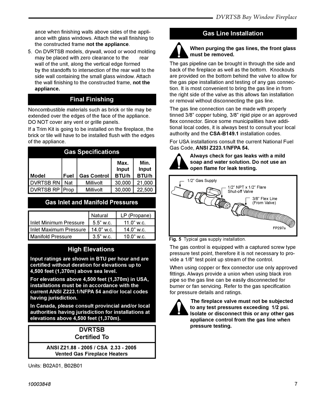
1/2” Gas Supply
1/2” NPT x 1/2” Flare
3/8” Flex Line
(From Valve)
FP297a
Fig. 5 Typical gas supply installation.
The gas control is equipped with a captured screw type pressure test point, therefore it is not necessary to pro- vide a 1/8” test point up stream of the control.
When using copper or flex connector use only approved fittings. Always provide a union when using black iron pipe so the gas line can be easily disconnected for burner or fan servicing. Refer to the gas specification for pressure details and ratings.
The fireplace valve must not be subjected to any test pressures exceeding 1/2 psi. Isolate or disconnect this or any other gas appliance control from the gas line when pressure testing.
10003848 | 7 |