Chateau™ Direct Vent Gas Fireplace
Clearance to Combustibles |
|
|
|
|
| Combustible | ||
|
|
|
|
| Framing and | |||
|
|
|
|
|
|
| ||
Top of Unit to Ceiling | 36” (914 mm) |
|
| � |
|
| Finish Wall Above | |
|
|
|
| Standoffs | ||||
Front of Unit to Combustibles (both sides) 36” (914 mm) |
|
| � |
|
| May use com- | ||
Appliance |
|
|
|
|
| bustible facing | ||
|
|
|
|
|
| |||
Top Standoffs | 0” (0 mm) |
|
|
|
|
| material in this | |
|
| � |
|
| area | |||
Bottom* | 0” (0 mm) |
|
|
|
| Standoff | ||
|
|
|
|
| ||||
Side Standoffs | 0” (0 mm) |
|
| � |
|
|
| |
Back Standoffs | 0” (0 mm) |
|
| � |
|
|
| |
Venting |
|
|
|
|
|
| ||
Horizontal Termination | � | � | � � � |
|
|
| ||
Vertical Sections: |
|
|
|
| ||||
|
|
|
|
|
|
| ||
Sides | 2¹⁄₂” (64 mm) |
|
|
|
|
|
| |
Horizontal Sections: |
| Noncombustible Finish Material |
|
|
| |||
Top | 3¹⁄₂” (89 mm) | (Such as Dura Rock) |
| Top of Sheet Metal | ||||
CFM146d |
| Fireplace Front | ||||||
Bottom | 1¹⁄₂” (38 mm) |
|
|
| ||||
|
| Mantel Chart |
| |||||
Sides | 2¹⁄₂” (64 mm) |
|
|
| ||||
| Mantel Shelf |
| Mantel from Top | |||||
Vertical Vent Application: |
|
|
| |||||
| Ref. | or Breast Plate | Ref. | of Comb. Chamber | ||||
Sides | 1¹⁄₂” (38 mm) | |||||||
|
| Depth |
|
|
| |||
|
|
|
|
|
|
| ||
* To prevent the potential for odors, do not use epoxy- | V | 10” | (254 mm) | A | 10” | (254 mm) | ||
filled particle board directly under this fireplace. | W | 9” | (229 mm) | B | 9” | (229 mm) | ||
|
| X | 8” | (203 mm) | C | 8” | (203 mm) | |
Mantels |
| Y | 7” | (178 mm) | D | 7” | (178 mm) | |
| Z | 6” | (152 mm) | E | 6” | (152 mm) | ||
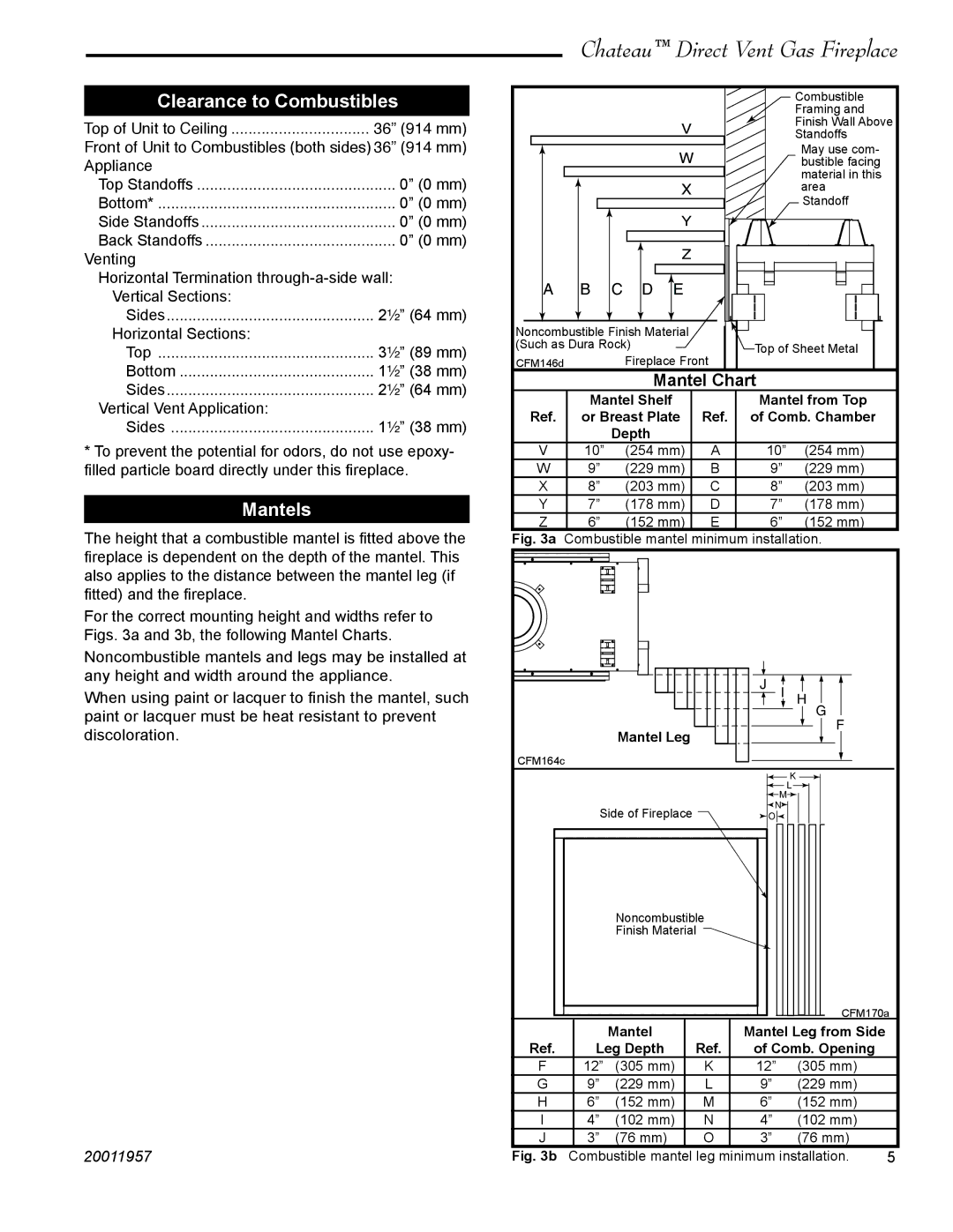
The height that a combustible mantel is fitted above the | ||||||||
Fig. 3a Combustible mantel minimum installation. | ||||||||
fireplace is dependent on the depth of the mantel. This |
|
|
|
|
|
| ||
also applies to the distance between the mantel leg (if |
|
|
|
|
|
| ||
fitted) and the fireplace. |
|
|
|
|
|
|
| |
For the correct mounting height and widths refer to |
|
|
|
|
|
| ||
Figs. 3a and 3b, the following Mantel Charts. |
|
|
|
|
|
| ||
Noncombustible mantels and legs may be installed at |
|
|
|
|
|
| ||
any height and width around the appliance. |
|
|
|
| � � |
| ||
When using paint or lacquer to finish the mantel, such |
|
|
|
| � | |||
paint or lacquer must be heat resistant to prevent |
|
|
|
|
| � | ||
|
|
|
|
| � | |||
discoloration. |
|
|
| Mantel Leg |
|
| ||
|
|
|
|
|
| |||
|
| CFM164c |
|
|
|
|
| |
|
|
|
|
|
|
| � | |
|
|
|
|
|
| � | � | |
|
|
|
|
|
|
| ||
|
|
| Side of Fireplace |
| � |
| ||
|
|
|
| � |
| |||
|
|
|
|
|
| Noncombustible |
|
|
|
|
|
|
| |
|
|
|
|
|
| Finish Material |
|
|
|
|
|
|
| |
|
|
|
|
|
|
|
|
|
|
|
|
| CFM170a | |
|
|
|
|
|
|
|
|
|
|
|
|
| ||
|
|
|
|
|
| Mantel |
| Mantel Leg from Side |
| |||||
|
| Ref. |
| Leg Depth | Ref. | of Comb. Opening |
| |||||||
|
| F |
| 12” | (305 mm) | K | 12” | (305 mm) |
| |||||
|
| G |
| 9” | (229 mm) | L |
| 9” | (229 mm) |
| ||||
|
| H |
| 6” | (152 mm) | M |
| 6” | (152 mm) |
| ||||
|
| I |
| 4” | (102 mm) | N |
| 4” | (102 mm) |
| ||||
|
| J |
| 3” | (76 mm) | O |
| 3” | (76 mm) |
| ||||
20011957 |
| Fig. 3b | Combustible mantel leg minimum installation. | 5 | ||||||||||
