Chateau™
Termination Clearances
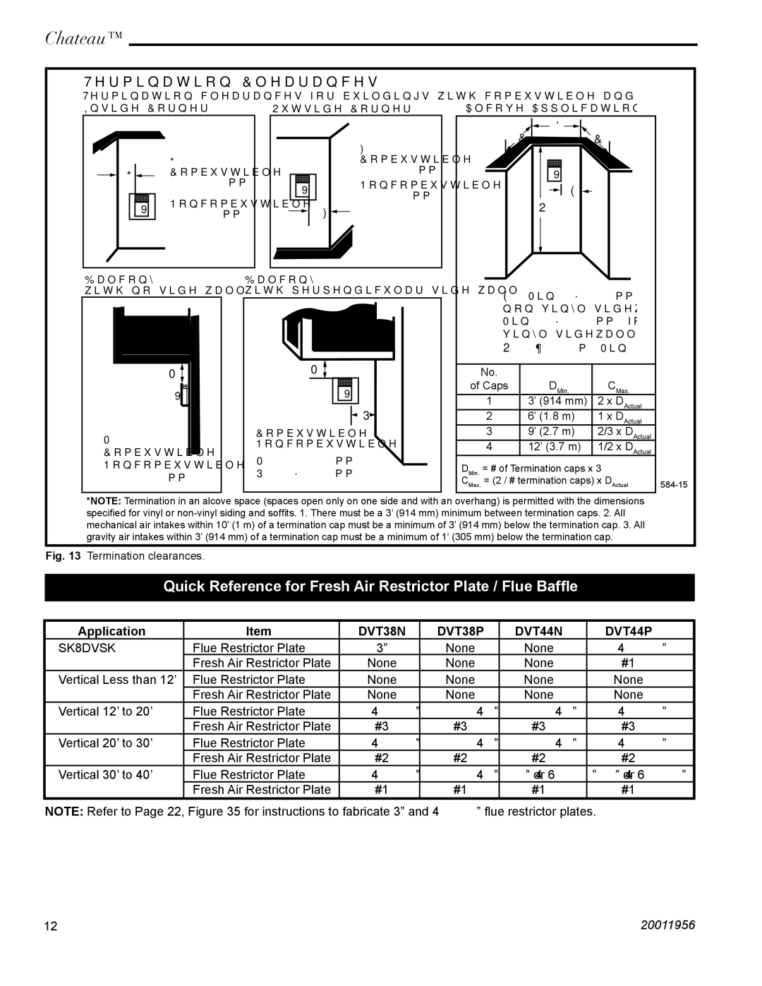
Termination clearances for buildings with combustible and noncombustible exteriors.
Inside Corner | Outside Corner | Alcove Applications* |
|
|
| F = |
|
| G = |
| Combustible | |
G | Combustible |
| 6" | (152 mm) |
| 6" (152 mm) | V | Noncombustible | |
|
| 2" | (51 mm) | |
| Noncombustible |
| ||
V |
| F |
| |
2" (51 mm) |
|
| ||
Balcony - | Balcony - |
with no side wall | with perpendicular side wall |
M | M | |
| ||
V | V | |
| P | |
M = | Combustible & | |
Noncombustible | ||
Combustible & | ||
M = 24" (610 mm) | ||
Noncombustible | ||
P = 20” (508 mm) | ||
12" (305 mm) |
![]()
![]() D
D ![]()
![]()
C C
V
![]()
![]() E
E ![]()
O
E = Min. 6” (152 mm) for
O = 8’ (2.4 m) Min.
No. |
|
|
of Caps | DMin. | CMax. |
1 | 3’ (914 mm) | 2 x DActual |
2 | 6’ (1.8 m) | 1 x DActual |
3 | 9’ (2.7 m) | 2/3 x DActual |
4 | 12’ (3.7 m) | 1/2 x DActual |
DMin. = # of Termination caps x 3
CMax. = (2 / # termination caps) x DActual
*NOTE: Termination in an alcove space (spaces open only on one side and with an overhang) is permitted with the dimensions specified for vinyl or
Fig. 13 Termination clearances.
Quick Reference for Fresh Air Restrictor Plate / Flue Baffle
Application | Item | DVT38N | DVT38P | DVT44N | DVT44P |
SK8DVSK | Flue Restrictor Plate | 3” | None | None | 4¹⁄₂” |
| Fresh Air Restrictor Plate | None | None | None | #1 |
Vertical Less than 12’ | Flue Restrictor Plate | None | None | None | None |
| Fresh Air Restrictor Plate | None | None | None | None |
Vertical 12’ to 20’ | Flue Restrictor Plate | 4¹⁄₂” | 4¹⁄₂” | 4¹⁄₂” | 4¹⁄₂” |
| Fresh Air Restrictor Plate | #3 | #3 | #3 | #3 |
Vertical 20’ to 30’ | Flue Restrictor Plate | 4¹⁄₂” | 4¹⁄₂” | 4¹⁄₂” | 4¹⁄₂” |
| Fresh Air Restrictor Plate | #2 | #2 | #2 | #2 |
Vertical 30’ to 40’ | Flue Restrictor Plate | 4¹⁄₂” | 4¹⁄₂” | 4¹⁄₂” or 6³⁄₄” | 4¹⁄₂” or 6³⁄₄” |
| Fresh Air Restrictor Plate | #1 | #1 | #1 | #1 |
NOTE: Refer to Page 22, Figure 35 for instructions to fabricate 3” and 4¹⁄₂” flue restrictor plates.
12 | 20011956 |