•The maximum number of 45° elbows permitted per side wall installation is two (2). These elbows can be installed in either the vertical or horizontal run. (Fig. 18)
•For each 45° elbow installed in the horizontal run, the length of the horizontal run MUST be reduced by 18” (45 cm). This does not apply if the 45° elbows are installed on the vertical part of the vent system. For each 90° elbow installed in the horizontal run, the length of the horizontal run MUST be reduced by 36” (914 mm).
•The maximum number of elbow degrees in a system is 270°. (Fig. 19)
| A | B |
10' |
| |
|
| |
(3m) |
|
|
|
| A + B = 17' (5.2m) |
FP1238
Fig. 18 Maximum vent run with elbows.
Example: In Figure 23 |
|
|
|
|
| 4 | |||||
| Elbow 1 | = | 90° |
| |||||||
|
|
|
|
|
|
| |||||
| Elbow 2 | = | 45° |
|
|
|
|
|
| ||
| Elbow 3 | = | 45° |
|
|
|
|
|
| ||
| Elbow 4 | = | 90° |
|
|
|
|
|
| ||
Total angular variation = | 270° |
|
|
|
|
| |||||
|
|
|
|
|
|
| 3 |
| |||
|
|
| 1 |
|
|
| 2 |
|
|
| |
|
|
|
|
|
|
|
|
|
|
| |
|
|
|
|
|
|
|
|
|
|
|
|
|
|
|
|
|
|
|
|
|
|
|
|
|
|
|
|
|
|
|
|
|
|
|
|
|
|
|
|
|
|
|
|
|
|
|
|
|
|
|
|
|
|
|
|
|
|
|
|
FP1239a
Fig. 19 Maximum number of elbow degrees.
Chateau™
Sidewall Installation
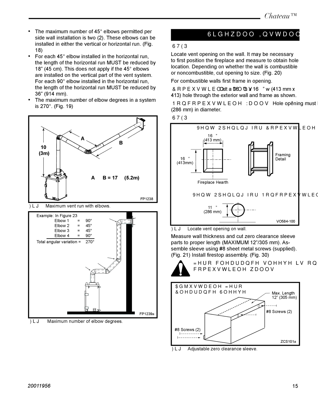
STEP 1
Locate vent opening on the wall. It may be necessary to first position the fireplace and measure to obtain hole location. Depending on whether the wall is combustible or noncombustible, cut opening to size. (Fig. 20)
For combustible walls first frame in opening.
Combustible Walls: Cut a 16¹⁄₄”h x 16¹⁄₄” w (413 mm x 413) hole through the exterior wall and frame as shown.
Noncombustible Walls: Hole opening must be 11¹⁄₄” (286 mm) in diameter.
STEP 2
Vent Opening for Combustible Wall
16¹⁄₄”
(413 mm)
16¹⁄₄” |
|
|
|
|
|
| Framing | |
|
|
|
| Detail | ||||
(413mm) |
|
|
|
|
| |||
|
|
|
|
|
|
|
|
|
|
|
|
|
|
|
|
|
|
|
|
|
|
|
|
|
|
|
Fireplace Hearth
Vent Opening for Noncombustible Wall
11¹⁄₄”
(286 mm)
Fig. 20 Locate vent opening on wall.
Measure wall thickness and cut zero clearance sleeve parts to proper length (MAXIMUM 12”/305 mm). As- semble sleeve using #8 sheet metal screws (supplied). (Fig. 21) Install firestop assembly. (Fig. 30)
Zero clearance sleeve is only required for combustible walls.
Adjustable Zero |
|
Clearance Sleeve | Max. Length |
| 12” (305 mm) |
| #8 Screws (2) |
#8 Screws (2) |
|
| ZCS101a |
Fig. 21 Adjustable zero clearance sleeve. |
|
20011956 | 15 |