Chateau™
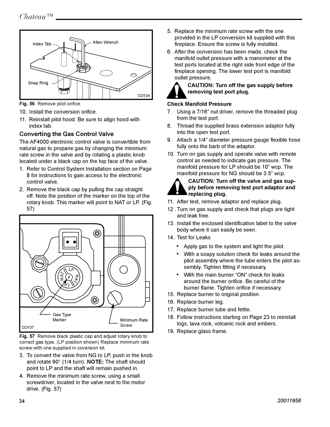
Index Tab | Allen Wrench |
|
Snap Ring
CO134
Fig. 56 Remove pilot orifice.
10.Install the conversion orifice.
11.Reinstall pilot hood. Be sure to align hood with index tab.
Converting the Gas Control Valve
The AF4000 electronic control valve is convertible from natural gas to propane gas by changing the minimum rate screw in the valve and by rotating a plastic knob located under a black cap on the top face of the valve.
1.Refer to Control System Installation section on Page 8 for instructions to gain access to the electronic control valve.
2.Remove the black cap by pulling the cap straight off. Note the position of the marker on the top of the rotary knob. This marker will point to NAT or LP. (Fig. 57)
| � |
|
|
� | � |
|
|
| � | ||
� |
| ||
� |
| � | � |
| � |
| |
|
|
| |
| � |
|
|
Gas Type |
|
Marker | Minimum Rate |
CO137 | Screw |
|
Fig. 57 Remove black plastic cap and adjust rotary knob to correct gas type. (LP position shown) Replace minimum rate screw with one supplied in coversion kit.
3.To convert the valve from NG to LP, push in the knob and rotate 90° (1/4 turn). NOTE: The shaft should point to LP and the shaft will remain pushed in.
4.Remove the minimum rate screw, using a small screwdriver, located in the valve next to the motor
drive. (Fig. 57)
5.Replace the minimum rate screw with the one provided in the LP conversion kit supplied with this fireplace. Ensure the screw is fully installed.
6.After the conversion has been made, check the manifold outlet pressure with a manometer at the test ports located at the right side front edge of the fireplace opening. The lower test port is manifold outlet pressure.
CAUTION: Turn off the gas supply before removing test port plug.
Check Manifold Pressure
7.Using a 7/16” nut driver, remove the threaded plug from the test port.
8.Thread the supplied brass extension adaptor fully into the open test port.
9.Attach a 1/4” diameter pressure gauge flexible hose fully onto the barb of the adaptor.
10.Turn on gas supply and operate valve with remote control as needed to indicate gas pressure. The manifold pressure for LP should be 10” wcp. The manifold pressure for NG should be 3.5” wcp.
CAUTION: Turn off the valve and gas sup- ply before removing test port adaptor and replacing plug.
11. After test, remove adaptor and replace plug.
12 . Turn on gas supply and check that plugs are tight and leak free.
13.Install the enclosed identification label to the valve body where it can easily be seen.
14.Test for Leaks
•Apply gas to the system and light the pilot.
•With a soapy solution check for leaks around the pilot assembly where the tube enters the pilot as- sembly. Tighten fitting if necessary.
•With the main burner “ON” check for leaks around the burner orifice. Be careful of the burner flame. Tighten orifice if necessary.
15.Replace burner to original position.
16.Replace burner leg.
17.Replace burner tube and fettle.
18.Follow instructions starting on Page 23 to reinstall logs, lava rock, volcanic rock and embers.
19.Replace glass frame.
34 | 20011956 |