Chateau™
|
|
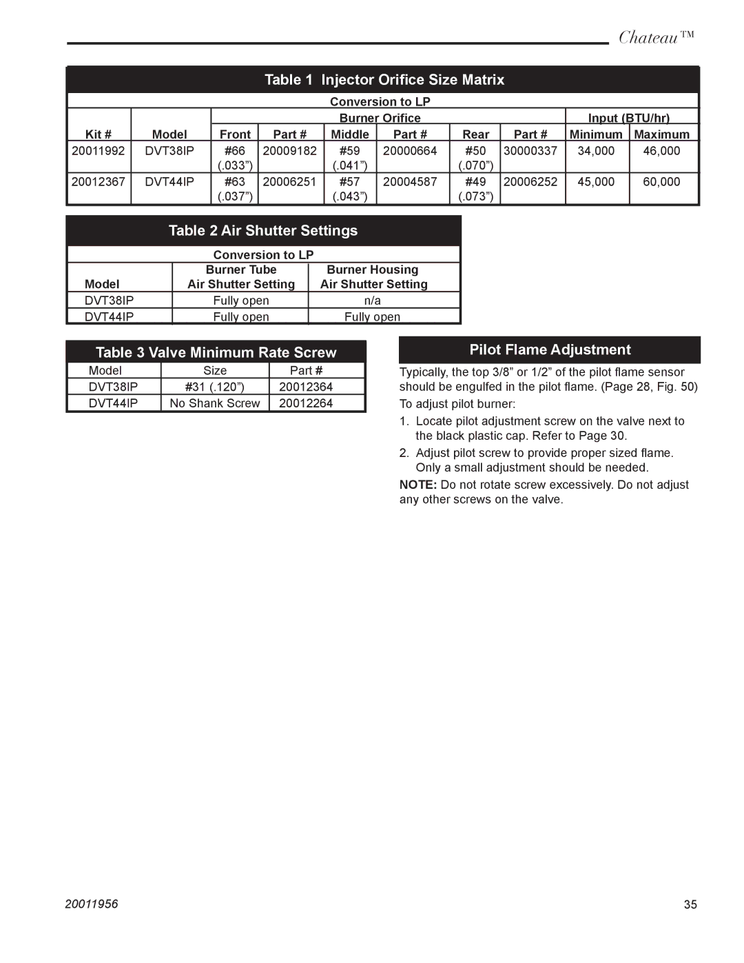
| Table 1 | Injector Orifice Size Matrix |
|
| ||||
|
|
|
|
|
|
|
|
|
|
|
|
|
|
|
| Conversion to LP |
|
|
|
| |
|
|
|
|
| Burner Orifice |
|
| Input (BTU/hr) | ||
Kit # | Model | Front | Part # |
| Middle | Part # | Rear | Part # | Minimum | Maximum |
20011992 | DVT38IP | #66 | 20009182 |
| #59 | 20000664 | #50 | 30000337 | 34,000 | 46,000 |
|
| (.033”) |
|
| (.041”) |
| (.070”) |
|
|
|
20012367 | DVT44IP | #63 | 20006251 |
| #57 | 20004587 | #49 | 20006252 | 45,000 | 60,000 |
|
| (.037”) |
|
| (.043”) |
| (.073”) |
|
|
|
Table 2 Air Shutter Settings
Conversion to LP
| Burner Tube | Burner Housing |
Model | Air Shutter Setting | Air Shutter Setting |
DVT38IP | Fully open | n/a |
DVT44IP | Fully open | Fully open |
Table 3 Valve Minimum Rate Screw
Model | Size | Part # |
DVT38IP | #31 (.120”) | 20012364 |
DVT44IP | No Shank Screw | 20012264 |
Pilot Flame Adjustment
Typically, the top 3/8” or 1/2” of the pilot flame sensor should be engulfed in the pilot flame. (Page 28, Fig. 50)
To adjust pilot burner:
1.Locate pilot adjustment screw on the valve next to the black plastic cap. Refer to Page 30.
2.Adjust pilot screw to provide proper sized flame. Only a small adjustment should be needed.
NOTE: Do not rotate screw excessively. Do not adjust any other screws on the valve.
20011956 | 35 |