Vermont Castings Jefferson Vent Free Gas Heater
Operation
Your First Fire
Read these instructions carefully and familiarize yourself with the burner controls of this heater.
The JUVSR uses a Honeywell control valve that allows thermostatic, on/off switch regulation and has a sepa- rate Piezo ignition button. (Fig. 20)
The JUVSM is equipped with an SIT control valve for manual use only.
Locate the Pilot assembly to the right behind the burner. (Fig. 21) Follow the lighting instructions on page 14 exactly.
For the first fire, allow the stove to operate continuously for six hours without using the fan. During the first fire, it is not unusual to smell some odor associated with new logs, paint and metal being heated. Odors should dissipate within a few hours or so, however, you can open a window to provide plenty of fresh air to alleviate this condition.
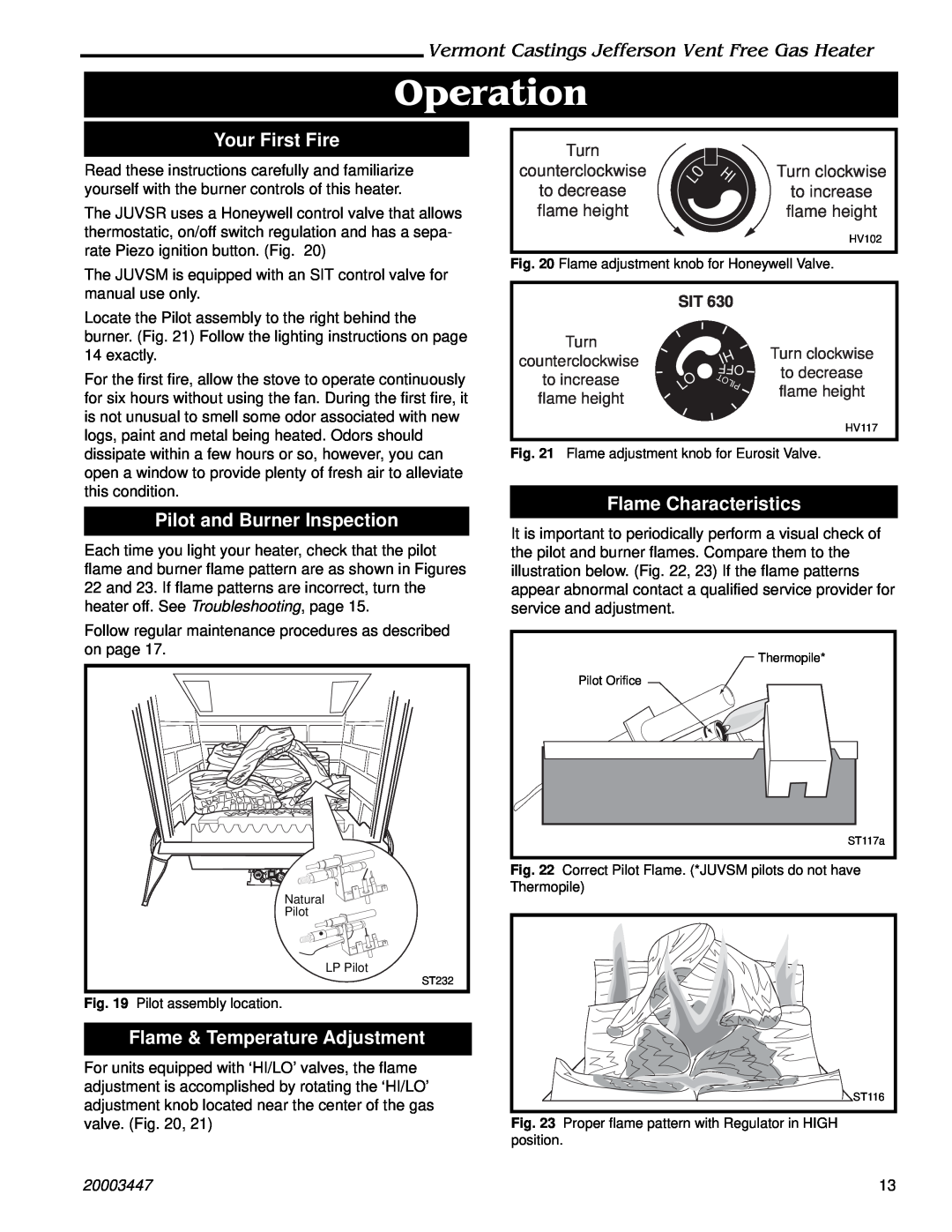
Pilot and Burner Inspection
Each time you light your heater, check that the pilot flame and burner flame pattern are as shown in Figures 22 and 23. If flame patterns are incorrect, turn the heater off. See Troubleshooting, page 15.
Follow regular maintenance procedures as described on page 17.
Natural
Pilot
LP Pilot
ST232
Fig. 19 Pilot assembly location.
Flame & Temperature Adjustment
For units equipped with ‘HI/LO’ valves, the flame adjustment is accomplished by rotating the ‘HI/LO’ adjustment knob located near the center of the gas valve. (Fig. 20, 21)
20003447
| Turn |
|
|
|
counterclockwise | LO | HI | Turn clockwise |
to decrease |
| to increase | |
|
| ||
flame height |
|
| flame height |
|
|
| HV102 |
Fig. 20 Flame adjustment knob for Honeywell Valve.
SIT 630
Turn
counterclockwise |
| HI | Turn clockwise | |
|
| |||
| OFF | to decrease | ||
| to increase |
| |||
LO | PILOT | |||
| flame height | ||||
flame height | ||||
| ||||
|
| |||
|
|
| ||
|
|
| HV117 |
Fig. 21 Flame adjustment knob for Eurosit Valve.
Flame Characteristics
It is important to periodically perform a visual check of the pilot and burner flames. Compare them to the illustration below. (Fig. 22, 23) If the flame patterns appear abnormal contact a qualified service provider for service and adjustment.
Thermopile* |
Pilot Orifice |
ST117a |
Fig. 22 Correct Pilot Flame. (*JUVSM pilots do not have Thermopile)
| ST116 |
Fig. 23 | Proper flame pattern with Regulator in HIGH |
position. |
|
| 13 |