Vermont Castings Jefferson Vent Free Gas Heater
Assembly Procedures
Unpack the Stove
Remove the stove assembly from the shipping carton and inspect it for loose or damaged parts. Do not install this appliance if any parts are loose or if there is any visual or suspected damage resulting from shipping or handling. Report damage to your dealer/distributor immediately. The log set is packaged in the box shipped inside the firebox.
To remove the packaged log set from the firebox:
•Lift the stove front up and then swing the bottom out and away to disengage it from the stove body. (Fig. 4) Cut the wire tie securing the screen.
•Remove the screen frame. (Fig. 5)
•Remove box and set aside.
Contact your dealer if the burner is loose or damaged in any way.
ST229b
Fig. 4 Remove stove front.
Screen Hooks
ST208b
Fig. 5 Lift screen from firebox.
20003447
WARNING
Failure to position the parts in accordance with these diagrams or failure to use only parts specifically approved for use with this heater may result in property damage or personal injury.
CAUTION
Porcelain enamelled surfaces are fragile. Handle porcelain enamelled castings tenderly. Familiarize yourself with the assembly steps before you begin and proceed with deliberation and care. If possible, have assistance available.
Place enamelled castings on a soft, cushioned surface until you are ready to assembly.
Avoid contact between the castings and other hard surfaces or objects.
Optional Fan Kit Installation (2960/FK28)
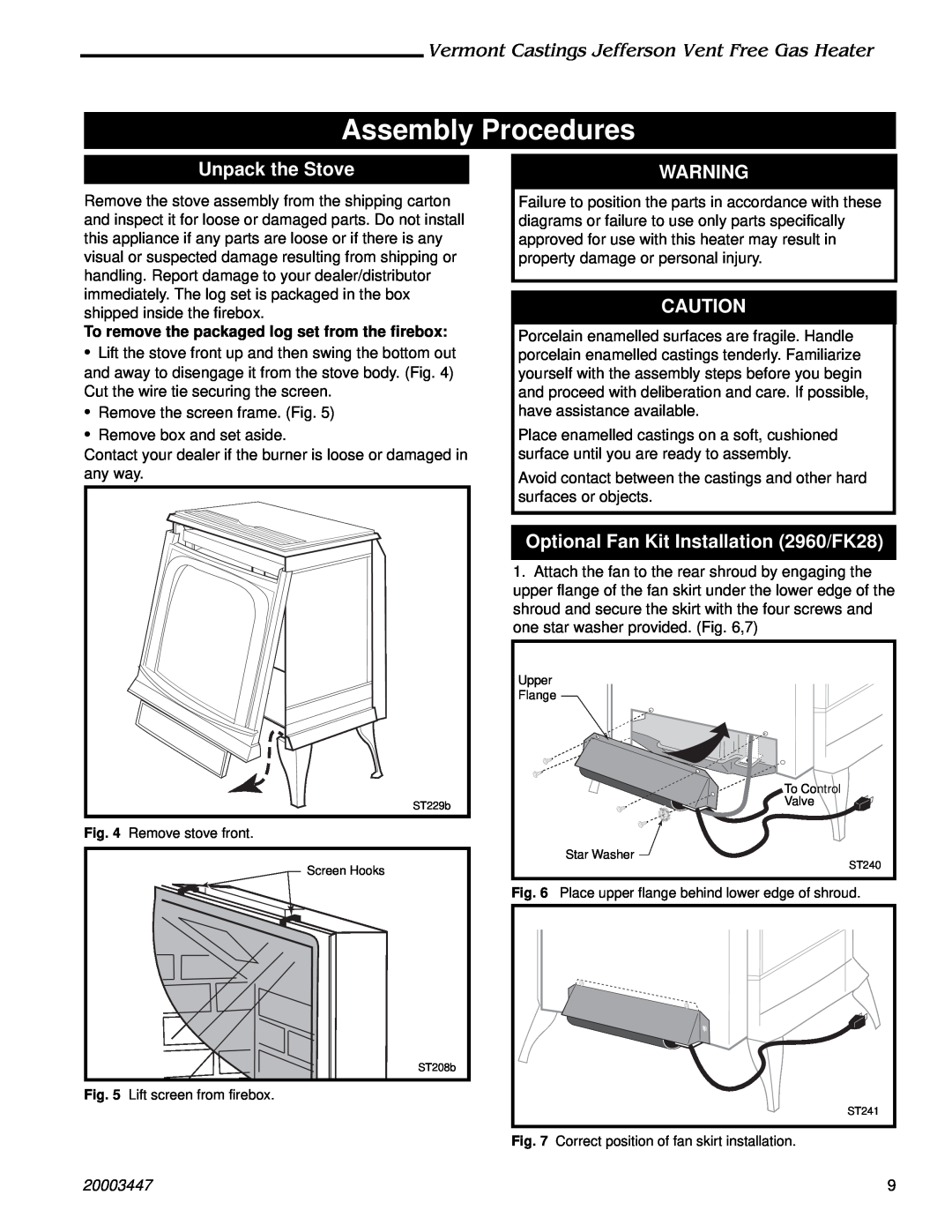
1.Attach the fan to the rear shroud by engaging the upper flange of the fan skirt under the lower edge of the shroud and secure the skirt with the four screws and one star washer provided. (Fig. 6,7)
Upper |
Flange |
To Control |
Valve |
Star Washer |
ST240 |
Fig. 6 Place upper flange behind lower edge of shroud.
| ST241 |
Fig. 7 | Correct position of fan skirt installation. |
| 9 |