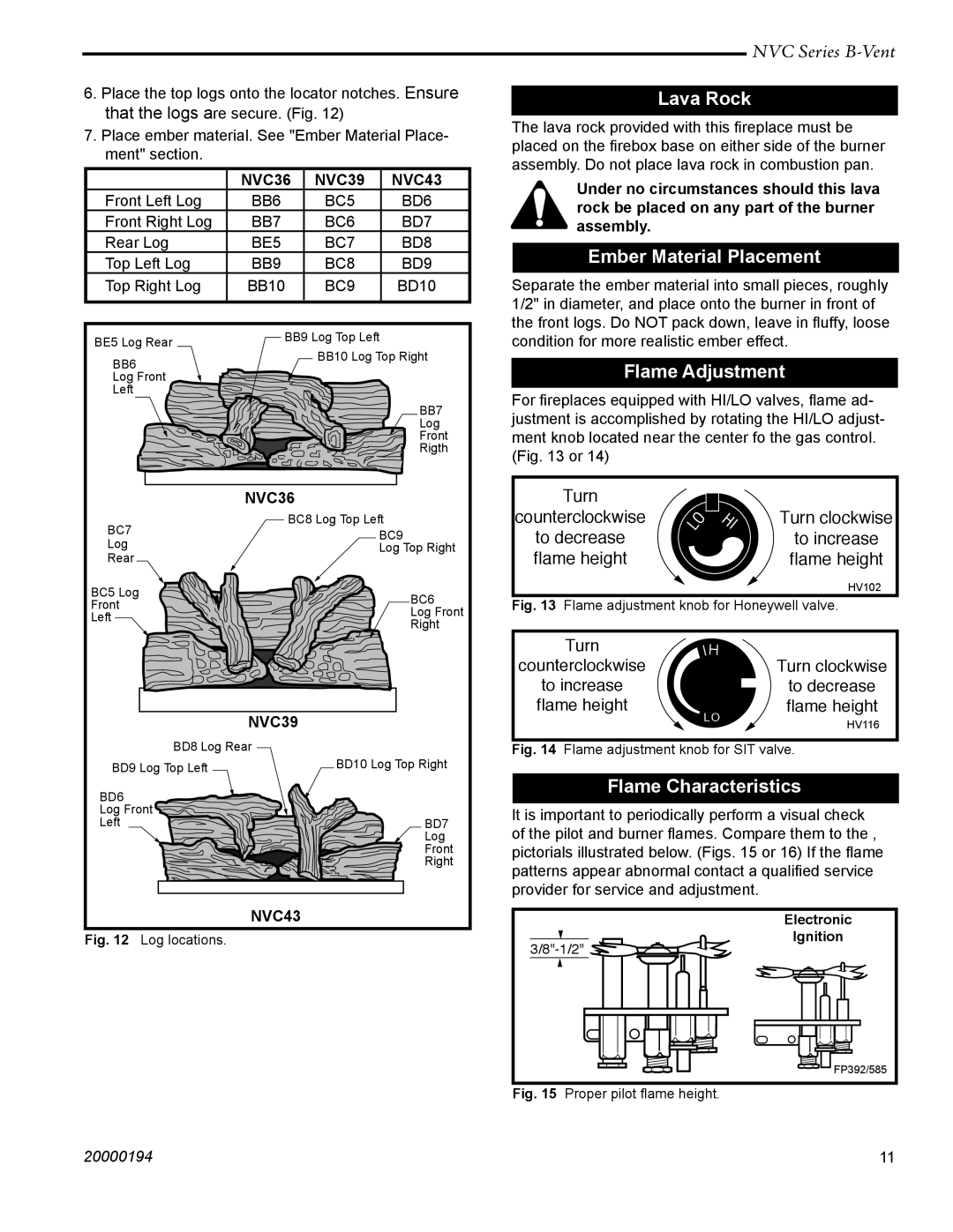
NVC39, NVC36, NVC43 specifications
Vermont Castings is known for its commitment to quality and craftsmanship, and its NVC series of gas stoves, including the NVC39, NVC36, and NVC43, exemplify this tradition. These models provide both warmth and aesthetic appeal, making them popular choices for homeowners seeking a blend of efficiency and style in their heating solutions.The NVC39 is designed for larger spaces, boasting a heating capacity that can warm up to 2,000 square feet, making it suitable for open-concept living areas or larger rooms. It features a generous viewing area, allowing residents to enjoy the mesmerizing flames while creating an inviting atmosphere. With an impressive efficiency rating, the NVC39 ensures that fuel consumption is minimized, resulting in lower heating costs.
Moving to the NVC36, this model offers a slightly more compact design without compromising on power. It is an ideal choice for medium-sized rooms and comes equipped with the same high-efficiency rating as the NVC39. This model is particularly favored for its easy-to-use controls, allowing users to adjust the flame and heat output effortlessly. Its stunning cast iron construction not only provides durability but also enhances the classic aesthetic Vermont Castings is renowned for.
The NVC43 is the largest of the trio, making it perfect for those looking for a powerful heating solution for extensive spaces. With its capable output, it can effectively heat areas over 2,500 square feet. Like its counterparts, the NVC43 integrates modern technology with traditional design. It features an advanced ignition system that ensures reliable starting every time. Furthermore, it is designed with an oxygen depletion sensor, prioritizing safety by automatically turning off the unit if oxygen levels drop to unsafe levels.
All three models come with customizable options, allowing the user to personalize their stove with various finishes and styles. Add-on features like ceramic glass doors and optional blowers enhance their functionality and aesthetics. In addition, they incorporate a burn system that maximizes heat output while minimizing emissions, aligning with Vermont Castings' commitment to environmental stewardship.
Overall, the Vermont Castings NVC series combines advanced technology, character, and efficiency, providing homeowners with versatile options that meet both heating needs and design preferences. They are ideal for anyone seeking the practicality of modern heating with the beauty of classic craftsmanship.