VIVOTEK - A Leading Provider of Multimedia Communication Solutions
DI/DO Diagram
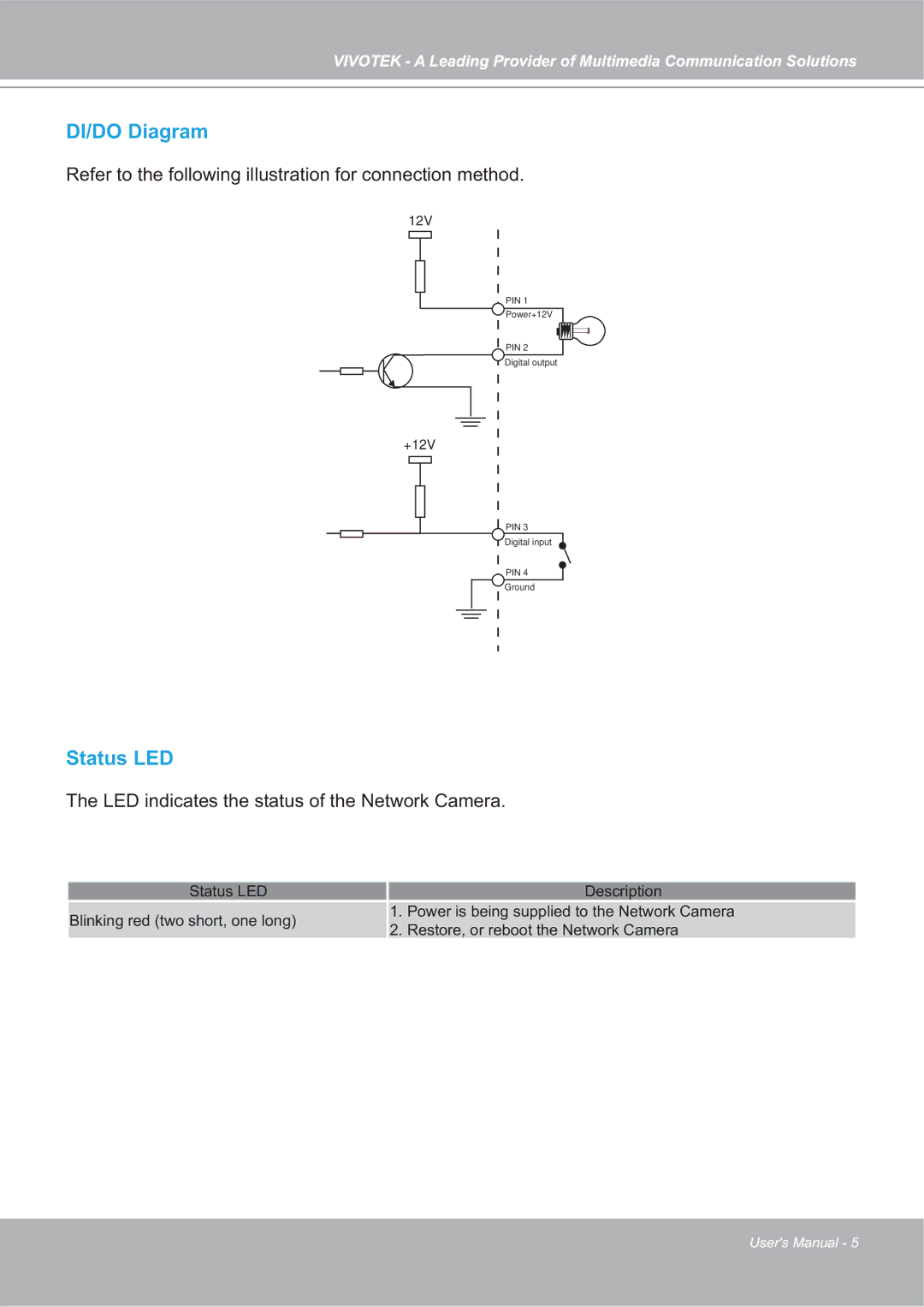
Refer to the following illustration for connection method.
12V
PIN 1
Power+12V
PIN 2
Digital output
+12V
PIN 3
Digital input
PIN 4
Ground
Status LED
The LED indicates the status of the Network Camera.
Status LED |
| Description | |
Blinking red (two short, one long) | 1. | Power is being supplied to the Network Camera | |
2. | Restore, or reboot the Network Camera | ||
|
User's Manual - 5