VIVOTEK
Network Deployment
General Connection (with PoE)
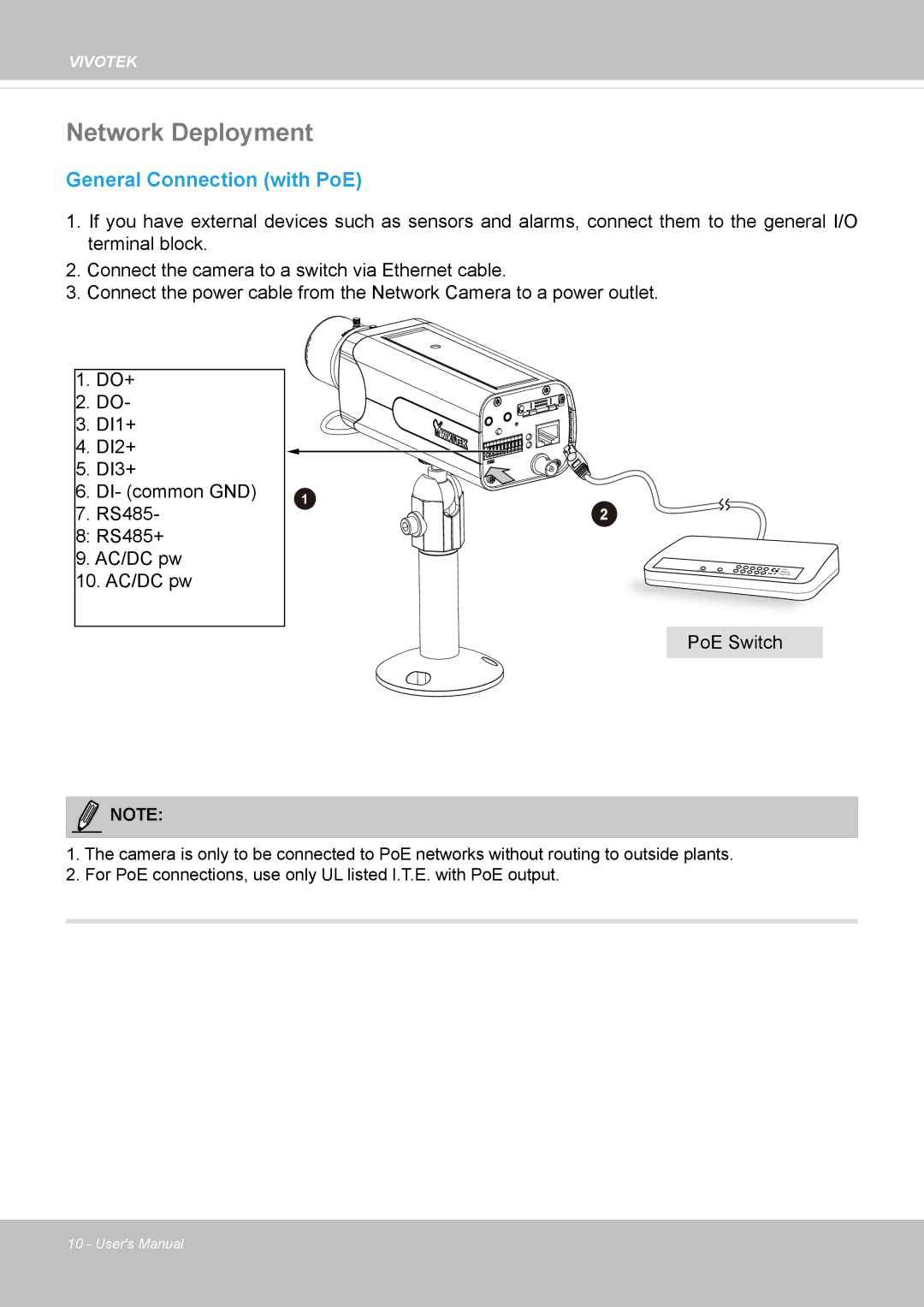
1.If you have external devices such as sensors and alarms, connect them to the general I/O terminal block.
2.Connect the camera to a switch via Ethernet cable.
3.Connect the power cable from the Network Camera to a power outlet.
1.DO+
2.DO-
3.DI1+
4.DI2+
5.DI3+
6.DI- (common GND)
7.RS485-
8:RS485+
9. AC/DC pw
10. AC/DC pw
1
2
POWER | COLLISION | 1 |
|
|
|
|
| 2 | 3 | 4 | 5 |
LINK |
RECEIVE |
PARTITION
PoE Switch
NOTE:
1.The camera is only to be connected to PoE networks without routing to outside plants.
2.For PoE connections, use only UL listed I.T.E. with PoE output.
10 - User's Manual