VIVOTEK - A Leading Provider of Multimedia Communication Solutions
Physical description
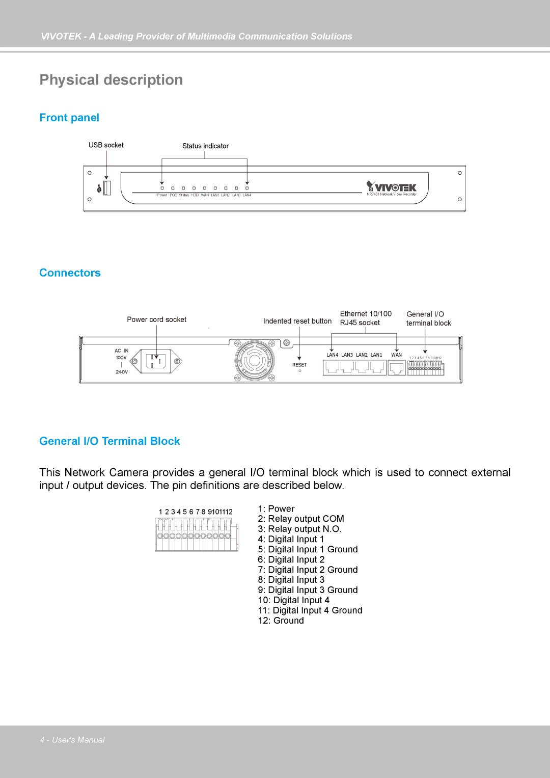
Front panel
USB socket | Status indicator |
Power | POE Status HDD WAN LAN1 LAN2 LAN3 LAN4 | NR7401 Network Video Recorder |
Connectors
Power cord socket | Indented reset button | Ethernet 10/100 | General I/O |
RJ45 socket | terminal block |
LAN4 LAN3 LAN2 LAN1 | WAN | 1 2 3 4 5 6 7 8 9101112 |
|
| |
RESET |
|
|
General I/O Terminal Block
This Network Camera provides a general I/O terminal block which is used to connect external input / output devices. The pin definitions are described below.
1 2 3 4 5 6 7 8 9101112 | 1: Power |
| 2: Relay output COM |
| 3: Relay output N.O. |
| 4: Digital Input 1 |
| 5: Digital Input 1 Ground |
6:Digital Input 2
7:Digital Input 2 Ground
8:Digital Input 3
9:Digital Input 3 Ground
10:Digital Input 4
11:Digital Input 4 Ground
12:Ground
4 - User's Manual