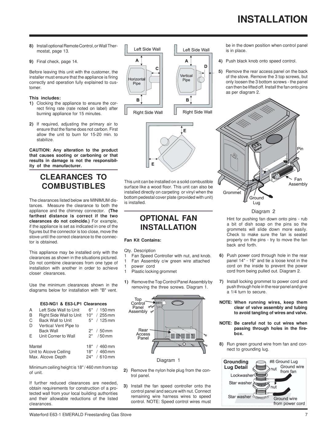
E63-NG1 specifications
Waterford Appliances has long been synonymous with quality and innovation in the kitchen appliance sector. Their E63-NG1 model embodies this legacy, combining cutting-edge technology with user-friendly design to deliver an exceptional cooking experience.The E63-NG1 is a gas range that stands out for its stunning appearance, featuring a robust stainless steel finish that not only enhances durability but also adds a touch of elegance to any kitchen. Its sleek design is complemented by heavy-duty cast iron grates, which provide a stable cooking surface that easily supports pots and pans of various sizes.
One of the standout features of the E63-NG1 is its powerful burners. The range boasts a total of five burners, including a high-output burner that generates up to 18,000 BTUs, allowing users to achieve rapid boiling and high-heat searing. Additionally, the other burners, with a variety of BTUs ranging from 6,000 to 15,000, offer versatility for simmering, sautéing, and delicate cooking tasks. This array of burners ensures that home chefs have the flexibility to tackle multiple dishes simultaneously, enhancing overall cooking efficiency.
The E63-NG1 is equipped with a spacious oven that provides ample cooking space, accommodating large roasts and multiple trays. The oven features advanced convection technology, which ensures even heat distribution for perfectly baked goods, while reducing cooking times. The inclusion of multiple oven modes, including bake, broil, and a specialized pizza mode, adds to the appliance's versatility, making it an ideal choice for various culinary styles and preferences.
Another notable characteristic of the E63-NG1 is its user-friendly digital controls. The intuitive interface allows for precise temperature settings and timing, making cooking more straightforward and enjoyable. Additionally, the oven includes dual interior lights, ensuring that users can easily monitor their food without opening the door, which helps maintain optimal cooking temperatures.
Safety is also a priority in the E63-NG1 design. It features an automatic shut-off function that activates if the oven is left on for an extended period, giving users peace of mind. The appliance also offers a reliable ignition system that ensures a quick and safe start every time.
In summary, the Waterford Appliances E63-NG1 is a perfect blend of style, functionality, and safety. With its powerful burners, spacious oven, and innovative technologies, this gas range stands out as an excellent addition to any kitchen, catering to both day-to-day meals and special culinary projects alike. Whether you're a novice home cook or an experienced chef, the E63-NG1 delivers the performance and reliability needed to inspire culinary creativity.

