INSTALLATION

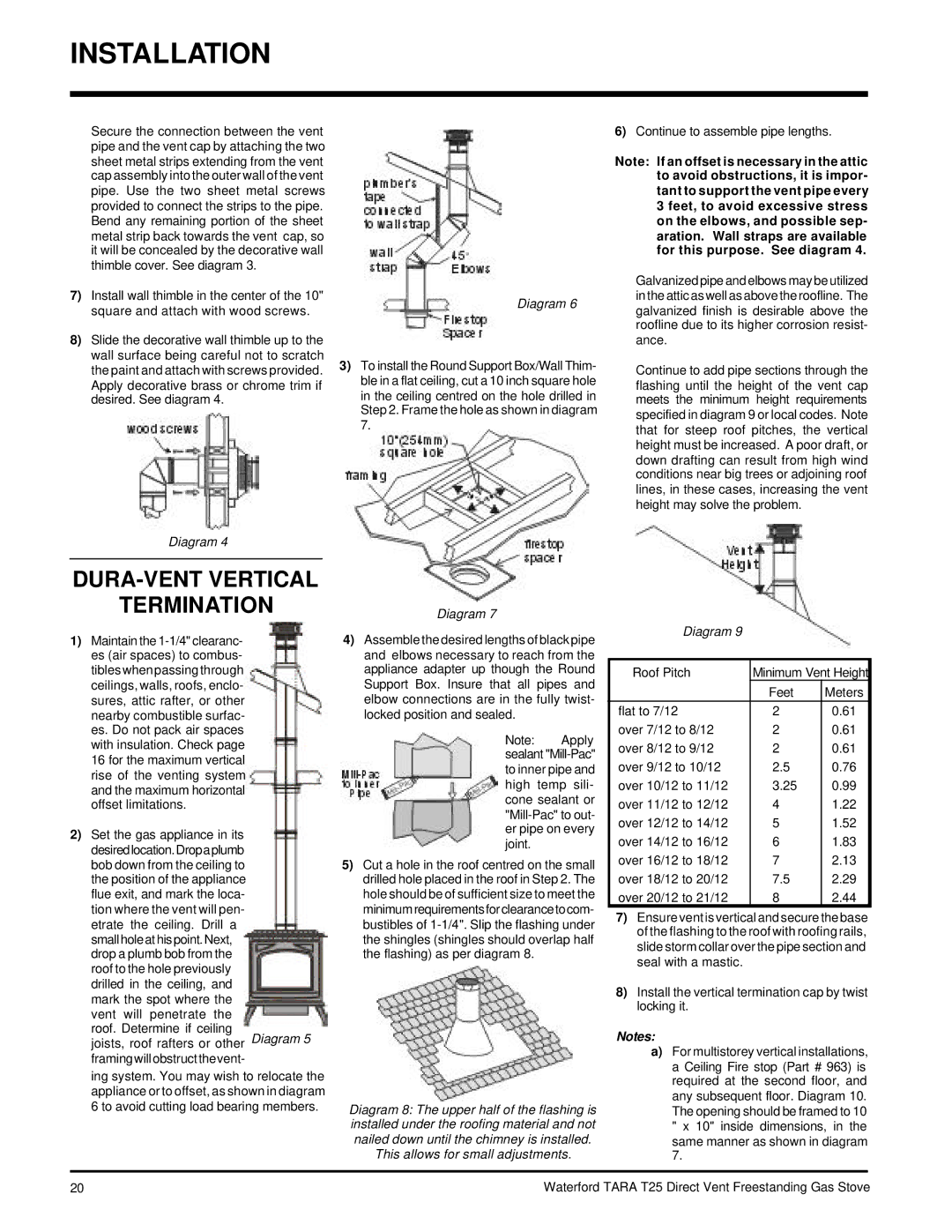
Secure the connection between the vent pipe and the vent cap by attaching the two sheet metal strips extending from the vent cap assembly into the outer wall of the vent pipe. Use the two sheet metal screws provided to connect the strips to the pipe. Bend any remaining portion of the sheet metal strip back towards the vent cap, so it will be concealed by the decorative wall thimble cover. See diagram 3.

7)Install wall thimble in the center of the 10" square and attach with wood screws.

8)Slide the decorative wall thimble up to the wall surface being careful not to scratch the paint and attach with screws provided. Apply decorative brass or chrome trim if desired. See diagram 4.

Diagram 6

3)To install the Round Support Box/Wall Thim- ble in a flat ceiling, cut a 10 inch square hole in the ceiling centred on the hole drilled in Step 2. Frame the hole as shown in diagram 7.

6)Continue to assemble pipe lengths.

Note: If an offset is necessary in the attic to avoid obstructions, it is impor- tant to support the vent pipe every 3 feet, to avoid excessive stress on the elbows, and possible sep- aration. Wall straps are available for this purpose. See diagram 4.

Galvanized pipe and elbows may be utilized in the attic as well as above the roofline. The galvanized finish is desirable above the roofline due to its higher corrosion resist- ance.

Continue to add pipe sections through the flashing until the height of the vent cap meets the minimum height requirements specified in diagram 9 or local codes. Note that for steep roof pitches, the vertical height must be increased. A poor draft, or down drafting can result from high wind conditions near big trees or adjoining roof lines, in these cases, increasing the vent height may solve the problem.

Diagram 4


DURA-VENT VERTICAL


TERMINATION

Diagram 7

1)Maintain the 1-1/4" clearanc- es (air spaces) to combus- tibleswhenpassingthrough ceilings, walls, roofs, enclo- sures, attic rafter, or other nearby combustible surfac- es. Do not pack air spaces with insulation. Check page

16 for the maximum vertical rise of the venting system and the maximum horizontal offset limitations.

2)Set the gas appliance in its desiredlocation.Dropaplumb bob down from the ceiling to the position of the appliance flue exit, and mark the loca- tion where the vent will pen- etrate the ceiling. Drill a small hole at his point. Next, drop a plumb bob from the roof to the hole previously drilled in the ceiling, and mark the spot where the vent will penetrate the

roof. Determine if ceiling

joists, roof rafters or other Diagram 5 framingwillobstructthevent-

ing system. You may wish to relocate the appliance or to offset, as shown in diagram 6 to avoid cutting load bearing members.

4)Assemble the desired lengths of black pipe and elbows necessary to reach from the appliance adapter up though the Round Support Box. Insure that all pipes and elbow connections are in the fully twist- locked position and sealed.

Note: Apply sealant "Mill-Pac" to inner pipe and high temp sili- cone sealant or "Mill-Pac" to out- er pipe on every joint.

5)Cut a hole in the roof centred on the small drilled hole placed in the roof in Step 2. The hole should be of sufficient size to meet the minimum requirements for clearance to com- bustibles of 1-1/4". Slip the flashing under the shingles (shingles should overlap half the flashing) as per diagram 8.

Diagram 8: The upper half of the flashing is installed under the roofing material and not nailed down until the chimney is installed.

This allows for small adjustments.

Diagram 9


Roof Pitch


Minimum Vent Height


Feet

Meters

flat to 7/12


2

0.61

over 7/12 to 8/12


2

0.61

over 8/12 to 9/12


2

0.61

over 9/12 to 10/12


2.5

0.76

over 10/12 to 11/12


3.25

0.99

over 11/12 to 12/12


4

1.22

over 12/12 to 14/12


5

1.52

over 14/12 to 16/12


6

1.83

over 16/12 to 18/12


7

2.13

over 18/12 to 20/12


7.5

2.29

over 20/12 to 21/12


8

2.44


7)Ensure vent is vertical and secure the base of the flashing to the roof with roofing rails, slide storm collar over the pipe section and seal with a mastic.

8)Install the vertical termination cap by twist locking it.

Notes:

a)For multistorey vertical installations, a Ceiling Fire stop (Part # 963) is required at the second floor, and any subsequent floor. Diagram 10. The opening should be framed to 10 " x 10" inside dimensions, in the same manner as shown in diagram 7.

20

Waterford TARA T25 Direct Vent Freestanding Gas Stove

Page 20
Image 20
Waterford Appliances T25-NG, T25-LP installation manual Termination

T25-LP, T25-NG specifications

Waterford Appliances presents the T25-LP and T25-NG, two exceptional models in the realm of gas fireplaces that combine elegance, efficiency, and advanced technology. These fireplaces are designed to create a warm and inviting ambiance in any living space, making them perfect for both modern and traditional homes.

The T25-LP (liquid propane) and T25-NG (natural gas) models feature a sleek design that seamlessly integrates into various interior settings. One of their standout characteristics is the expansive viewing area, which allows for an unobstructed view of the mesmerizing flames. The clean lines and contemporary aesthetics of the T25 series make them a striking focal point in any room.

Functional elegance is enhanced by the innovative Multi-Stage Burner System, which produces a realistic flame pattern and optimal heat output. This technology ensures that both models deliver a beautiful, natural fire while also prioritizing efficiency. With adjustable flame heights, users can customize their experience to suit their mood, whether they desire a soft glow for a cozy evening or a higher flame for more substantial heating.

Energy efficiency is another key feature of the T25 series. Both models have been designed with high-efficiency ratings, allowing homeowners to enjoy warmth without excessive energy consumption. This not only contributes to lower utility bills but also aligns with environmentally conscious living. The incorporation of electronic ignition ensures a hassle-free start-up process, with the option for a remote control that enhances convenience.

Additionally, the T25 fireplaces are equipped with advanced safety features, including a built-in pressure regulator and safety shut-off valves, providing peace of mind for users. The fireplaces also come with a range of customizable options such as decorative media, including glass and logs, allowing homeowners to tailor the look of their fireplace to their personal style.

The T25-LP and T25-NG models stand out not only for their beauty but also for their performance and reliability. With user-friendly controls and durable construction, these fireplaces provide lasting enjoyment and comfort. Waterford Appliances has engineered these units to be low-maintenance while ensuring high-end performance, making them a superior choice for anyone looking to enhance their living environment with warmth and style. Overall, with cutting-edge technology, elegant design, and user-centered functionality, the T25 series is a remarkable addition to any home.