I

Setting Trolley Close Position/

Connecting Door Arm

(Models 9100, 9400, 9600, 5120, 5140 & 9700)

With TorqueMaster® Or Extension Springs


Tools Needed:

DETERMINE THE WAYNE-DALTON TRACK


RADIUS BEING USED:

Needle Nose Pliers

FOR MOUNT HOPE AND PENSACOLA


TRACK:

Adjustable Wrench

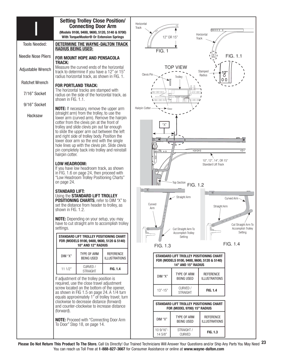
Measure the curved ends of the horizontal


track to determine if you have a 12” or 15”


radius horizontal track, as shown in FIG. 1.

Ratchet Wrench

FOR PORTLAND TRACK:


7/16” Socket

The horizontal tracks are stamped with

radius on the side of the horizontal track, as


shown in FIG. 1.1.

9/16” Socket

NOTE: If necessary, remove the upper arm


Hacksaw

(straight arm) from the trolley, to use the

lower arm (curved arm). Remove the hairpin


cotter from the clevis pin at the front of


trolley and slide clevis pin out far enough


to slide the upper arm out between the left


and right side of trolley body. Position the


lower door arm so the end with the single


hole lines up with the clevis pin. Slide clevis


pin completely back into trolley and reinstall


hairpin cotter.


LOW HEADROOM:


If you have low headroom track, as shown

Horizontal

Track

Horizontal

12” OR 15”

Track


FIG. 1


FIG. 1.1


12”


TOP VIEW

Stamped


Clevis Pin


12”

Trolley

Radius


Hairpin Cotter

“X”

10”, 12”, 14”, OR 15” Standard Lift Track

in FIG. 1.6 on page 24, then proceed with

“Low Headroom Trolley Positioning Charts”

on page 24.

STANDARD LIFT:

Using the STANDARD LIFT TROLLEY

POSITIONING CHARTS, refer to DIM “X” to

set the distance from header to trolley, as

shown in FIG. 1.2.

NOTE: Depending on your setup, you may

have to cut straight arm to accomplish trolley

settings.

STANDARD LIFT TROLLEY POSITIONING CHART

FOR (MODELS 9100, 9400, 9600, 5120 & 5140)

Top Section

FIG. 1.2

Straight Arm

Curved

Arm

Cut Straight Arm To

Accomplish Trolley

Setting

Curved Arm

Straight Arm

Cut Straight Arm To

Accomplish Trolley

Setting


10” AND 12” RADIUS


DIM “X”

TYPE OF ARM

REFERENCE


BEING USED

ILLUSTRATIONS


11 1/2”

CURVED /

FIG. 1.4


STRAIGHT


If adjustment of the trolley position is

required, use the close travel adjustment

screw located on the bottom of the opener,

as shown in FIG 1.5 on page 24. A 1/4 turn

equals approximately 1” of trolley travel; turn

clockwise to decrease distance (forward)

and counter-clockwise to increase distance

(forward).


NOTE: Proceed with “Connecting Door Arm

To Door” Step 18, on page 14.

FIG. 1.3

FIG. 1.4


STANDARD LIFT TROLLEY POSITIONING CHART FOR (MODELS 9100, 9400, 9600, 5120 & 5140)

14” AND 15” RADIUS

DIM “X”

TYPE OF ARM

REFERENCE

BEING USED

ILLUSTRATIONS


13”-15”

CURVED /

FIG. 1.4

STRAIGHT


STANDARD LIFT TROLLEY POSITIONING CHART

FOR (MODEL 9700) 15” RADIUS

DIM “X”

TYPE OF ARM

REFERENCE

BEING USED

ILLUSTRATIONS


10 9/16”-

STRAIGHT /

FIG. 1.3

14 5/8”

CURVED


Please Do Not Return This Product To The Store. Call Us Directly! Our Trained Technicians Will Answer Your Questions and/or Ship Any Parts You May Need 23 You can reach us Toll Free at 1-888-827-3667 for Consumer Assistance or online at www.wayne-dalton.com

Page 29
Image 29
Wayne-Dalton 3324B-Z installation instructions Radius Being Used, For Portland Track, LOW Headroom, Standard Lift

3324B-Z specifications

Wayne-Dalton is renowned for its commitment to innovative door solutions, and the Wayne-Dalton 3324B-Z is a prime example of their cutting-edge offerings in the realm of garage doors. This model is designed for residential settings, combining aesthetics with functionality.

One of the standout features of the 3324B-Z is its construction. The door is made from high-quality steel, ensuring exceptional durability and resistance to external elements. This steel is reinforced to provide strength and support, which is critical for maintaining the stability of the door over time. Moreover, the door is insulated with polyurethane, offering enhanced thermal efficiency. This insulation not only helps to regulate temperature within the garage but also contributes to energy savings by reducing heating and cooling costs.

Aesthetic appeal is another hallmark of the Wayne-Dalton 3324B-Z. Featuring a contemporary design, it is available in multiple color options and finishes, allowing homeowners to customize the look of their home while enhancing curb appeal. The door's design includes raised panel sections that add depth and texture, making it visually appealing without compromising on functionality.

In terms of technology, the Wayne-Dalton 3324B-Z integrates various advancements to enhance user experience and safety. It is equipped with a reliable spring system that promotes smooth operation and extends the lifespan of the door. The door can also be paired with Wayne-Dalton's innovative Quantum garage door opener, which features advanced security and remote access capabilities, allowing homeowners to operate their doors from anywhere via a smartphone app.

Safety is a paramount consideration in the design of the 3324B-Z. The door incorporates features such as pinch-resistant design, reinforced hinges, and safety sensors to protect users and pets from potential accidents during operation.

Installation and maintenance are also simplified with the Wayne-Dalton 3324B-Z. The door comes with detailed instructions for easy setup, and its durable materials require minimal upkeep, ensuring a long-lasting performance with minimal hassle.

In conclusion, the Wayne-Dalton 3324B-Z is a sophisticated choice for any homeowner seeking a balance of style, durability, and advanced technology. Its robust construction, attractive design, and safety features make it an ideal addition to modern homes. Whether upgrading an existing garage door or installing a new one, the 3324B-Z is a solution that stands out in functionality and aesthetics.