I

Configuración de la posición de

Riel


horizontal


cierre del trole / Conexión del


brazo de la puerta (Modelos 9100, 9400,

12˝ Ó 15˝

Riel


9600, 5120, 5140 y 9700) con resortes de torsión

horizontal


Herramientas

DETERMINAR EL RADIO DE RIEL

FIG. 1


necesarias:

WAYNE-DALTON UTILIZADO:


12”

FIG. 1.1


PARA LOS RIELES MOUNT HOPE Y

VISTA SUPERIOR


Alicates de punta


Radio


PENSACOLA:


Pasador


de aguja

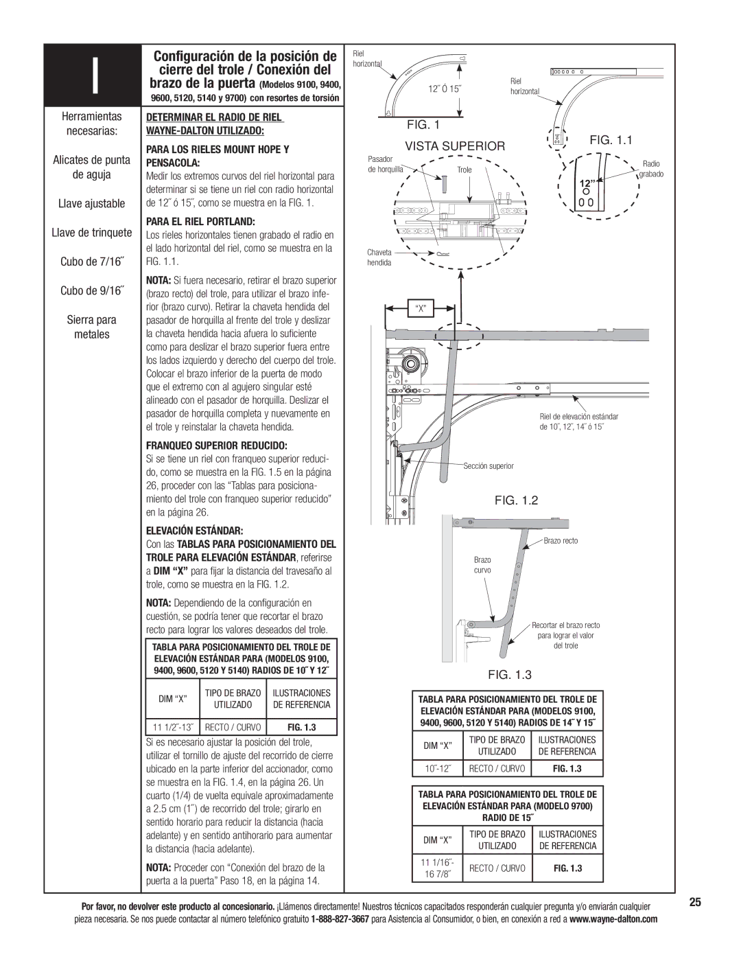
Medir los extremos curvos del riel horizontal para

de horquilla

Trole


grabado


determinar si se tiene un riel con radio horizontal


12”


Llave ajustable

de 12˝ ó 15˝, como se muestra en la FIG. 1.


Llave de trinquete

PARA EL RIEL PORTLAND:


Los rieles horizontales tienen grabado el radio en


el lado horizontal del riel, como se muestra en la

Chaveta


Cubo de 7/16˝

FIG. 1.1.


hendida


Cubo de 9/16˝

NOTA: Si fuera necesario, retirar el brazo superior


(brazo recto) del trole, para utilizar el brazo infe-


Sierra para

rior (brazo curvo). Retirar la chaveta hendida del

“X”


pasador de horquilla al frente del trole y deslizar


metales

la chaveta hendida hacia afuera lo suficiente


como para deslizar el brazo superior fuera entre


los lados izquierdo y derecho del cuerpo del trole.


Colocar el brazo inferior de la puerta de modo


que el extremo con al agujero singular esté


alineado con el pasador de horquilla. Deslizar el


pasador de horquilla completa y nuevamente en


Riel de elevación estándar


el trole y reinstalar la chaveta hendida.


de 10˝, 12˝, 14˝ ó 15˝


FRANQUEO SUPERIOR REDUCIDO:


Si se tiene un riel con franqueo superior reduci-


Sección superior


do, como se muestra en la FIG. 1.5 en la página


26, proceder con las “Tablas para posiciona-


miento del trole con franqueo superior reducido”


FIG. 1.2


en la página 26.


ELEVACIÓN ESTÁNDAR:


Brazo recto


Con las TABLAS PARA POSICIONAMIENTO DEL


TROLE PARA ELEVACIÓN ESTÁNDAR, referirse


Brazo


a DIM “X” para fijar la distancia del travesaño al


curvo


trole, como se muestra en la FIG. 1.2.


NOTA: Dependiendo de la configuración en


cuestión, se podría tener que recortar el brazo


Recortar el brazo recto


recto para lograr los valores deseados del trole.


para lograr el valor


TABLA PARA POSICIONAMIENTO DEL TROLE DE


del trole


ELEVACIÓN ESTÁNDAR PARA (MODELOS 9100,


9400, 9600, 5120 Y 5140) RADIOS DE 10˝ Y 12˝


FIG. 1.3


DIM “X”

TIPO DE BRAZO

ILUSTRACIONES

TABLA PARA POSICIONAMIENTO DEL TROLE DE


UTILIZADO

DE REFERENCIA


ELEVACIÓN ESTÁNDAR PARA (MODELOS 9100,


11 1/2˝-13˝ RECTO / CURVO

FIG. 1.3

9400, 9600, 5120 Y 5140) RADIOS DE 14˝ Y 15˝


Si es necesario ajustar la posición del trole,

DIM “X”


TIPO DE BRAZO

ILUSTRACIONES


utilizar el tornillo de ajuste del recorrido de cierre


UTILIZADO

DE REFERENCIA


ubicado en la parte inferior del accionador, como

10˝-12˝


RECTO / CURVO

FIG. 1.3


se muestra en la FIG. 1.4, en la página 26. Un


cuarto (1/4) de vuelta equivale aproximadamente

TABLA PARA POSICIONAMIENTO DEL TROLE DE


a 2.5 cm (1˝ ) de recorrido del trole; girarlo en

ELEVACIÓN ESTÁNDAR PARA (MODELO 9700)


sentido horario para reducir la distancia (hacia


RADIO DE 15˝


adelante) y en sentido antihorario para aumentar

DIM “X”


TIPO DE BRAZO

ILUSTRACIONES


la distancia (hacia adelante).


UTILIZADO

DE REFERENCIA


NOTA: Proceder con “Conexión del brazo de la

11 1/16˝-


RECTO / CURVO

FIG. 1.3


16 7/8˝


puerta a la puerta” Paso 18, en la página 14.


Por favor, no devolver este producto al concesionario. ¡Llámenos directamente! Nuestros técnicos capacitados responderán cualquier pregunta y/o enviarán cualquier

25


pieza necesaria. Se nos puede contactar al número telefónico gratuito 1-888-827-3667 para Asistencia al Consumidor, o bien, en conexión a red a www.wayne-dalton.com


Page 79
Image 79
Wayne-Dalton 3324B-Z Configuración de la posición de, Cierre del trole / Conexión del, En la página

3324B-Z specifications

Wayne-Dalton is renowned for its commitment to innovative door solutions, and the Wayne-Dalton 3324B-Z is a prime example of their cutting-edge offerings in the realm of garage doors. This model is designed for residential settings, combining aesthetics with functionality.

One of the standout features of the 3324B-Z is its construction. The door is made from high-quality steel, ensuring exceptional durability and resistance to external elements. This steel is reinforced to provide strength and support, which is critical for maintaining the stability of the door over time. Moreover, the door is insulated with polyurethane, offering enhanced thermal efficiency. This insulation not only helps to regulate temperature within the garage but also contributes to energy savings by reducing heating and cooling costs.

Aesthetic appeal is another hallmark of the Wayne-Dalton 3324B-Z. Featuring a contemporary design, it is available in multiple color options and finishes, allowing homeowners to customize the look of their home while enhancing curb appeal. The door's design includes raised panel sections that add depth and texture, making it visually appealing without compromising on functionality.

In terms of technology, the Wayne-Dalton 3324B-Z integrates various advancements to enhance user experience and safety. It is equipped with a reliable spring system that promotes smooth operation and extends the lifespan of the door. The door can also be paired with Wayne-Dalton's innovative Quantum garage door opener, which features advanced security and remote access capabilities, allowing homeowners to operate their doors from anywhere via a smartphone app.

Safety is a paramount consideration in the design of the 3324B-Z. The door incorporates features such as pinch-resistant design, reinforced hinges, and safety sensors to protect users and pets from potential accidents during operation.

Installation and maintenance are also simplified with the Wayne-Dalton 3324B-Z. The door comes with detailed instructions for easy setup, and its durable materials require minimal upkeep, ensuring a long-lasting performance with minimal hassle.

In conclusion, the Wayne-Dalton 3324B-Z is a sophisticated choice for any homeowner seeking a balance of style, durability, and advanced technology. Its robust construction, attractive design, and safety features make it an ideal addition to modern homes. Whether upgrading an existing garage door or installing a new one, the 3324B-Z is a solution that stands out in functionality and aesthetics.