1.Before beginning, make sure that you have read and understood the information on page 4.
Locate and open the parts bag labeled "FRAME
ASSEMBLY."
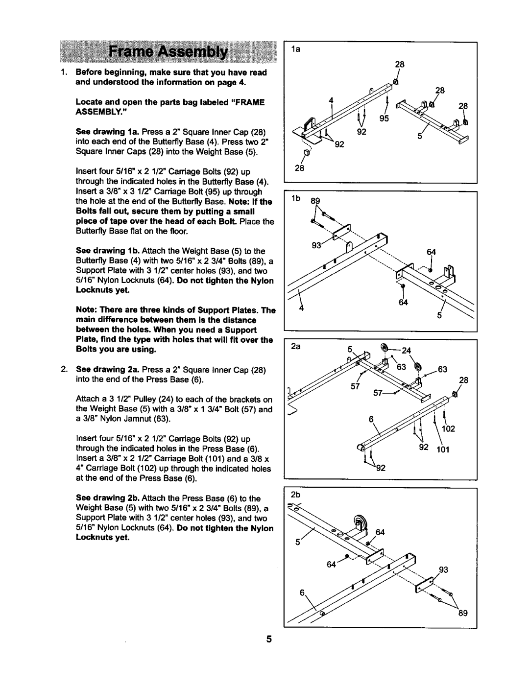
See drawing la. Press a 2" Square Inner Cap (28) into each end of the Butterfly Base (4). Press two 2" Square Inner Caps (28) into the Weight Base (5).
Insert four 5/16" x 2 1/2" Carriage Bolts (92) up through the indicated holes in the Butterfly Base (4). Insert a 3/8" x 3 1/2" Carriage Bolt (95) up through the hole at the end of the ButterflyBase. Note: If the Bolts fall out, secure them by putting a small piece of tape over the head of each Bolt. Place the Butterfly Base fiat on the floor.
See drawing lb. Attach the Weight Base (5) to the Butterfly Base (4) with two 5/16" x 2 3/4" Bolts (89), a Support Plate with 3 1/2" center holes (93), and two
5/16" Nylon Locknuts (64). Do not tighten the Nylon Locknuts yet.
Note: There are three kinds of Support Plates. The main difference between them is the distance
between the holes. When you need a Support Plate, find the type with holes that will fit over the Bolts you are using.
2, | See drawing 2a. Press a 2" Square Inner Cap (28) |
| |
| into the end of the Press Base (6). |
| Attach a 3 1/2" Pulley (24) to each of the brackets on |
| the Weight Base (5) with a 3/8" x 1 3/4" Bolt (57) and |
| a 318"Nylon Jamnut (63). |
| Insert four 5/16" x 2 1/2" Carriage Bolts (92) up |
| through the indicated holes in the Press Base (6). |
| Insert a 3/8" x 2 1/2" Carriage Bolt (101) and a 318 x |
| 4" Carriage Bolt (102) up through the indicated holes |
| at the end of the Press Base (6). |
| See drawing 2b. Attach the Press Base (6) to the |
| Weight Base (5) with two 5/16" x 2 3/4" Bolts (89), a |
| Support Plate with 3 1/2" center holes (93), and two |
| 5/16" Nylon Locknuts (64). Do not tighten the Nylon |
| Locknuts yet. |
la
28
4
92
28
lb 89
64
5
2a
28
102
92 101
2b
64
93
89
5