TROUBLE-SHOOTING AND MAINTENANCE
TIGHTENING THE CABLES
Woven cable, the type of cable used on the weight system, can stretch slightly when it is first used. If there is slack in the cables before resistance is felt, the cables should be tightened. If any slack is felt when using the front weight stack, both the High Cable (58) and the Low Cable (23) will need to be tightened. If any slack is felt when using the rear weight stack, both the Military Press Cable (72) and the Leg Press Cable (78) will need to be tightened.
To tighten the cables, insert the weight pin into the middle of the weight stack. Slack can be removed from these cables several ways:
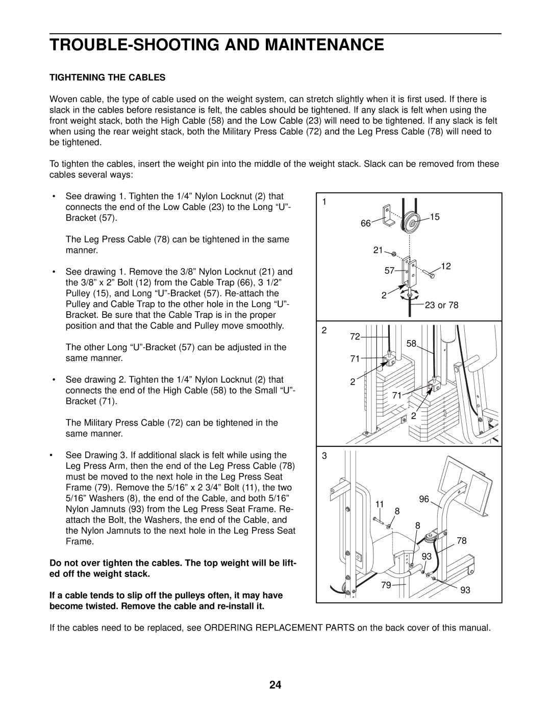
•See drawing 1. Tighten the 1/4” Nylon Locknut (2) that connects the end of the Low Cable (23) to the Long “U”- Bracket (57).
The Leg Press Cable (78) can be tightened in the same manner.
•See drawing 1. Remove the 3/8” Nylon Locknut (21) and the 3/8” x 2” Bolt (12) from the Cable Trap (66), 3 1/2” Pulley (15), and Long
The other Long
•See drawing 2. Tighten the 1/4” Nylon Locknut (2) that connects the end of the High Cable (58) to the Small “U”- Bracket (71).
The Military Press Cable (72) can be tightened in the same manner.
•See Drawing 3. If additional slack is felt while using the Leg Press Arm, then the end of the Leg Press Cable (78) must be moved to the next hole in the Leg Press Seat Frame (79). Remove the 5/16” x 2 3/4” Bolt (11), the two 5/16” Washers (8), the end of the Cable, and both 5/16” Nylon Jamnuts (93) from the Leg Press Seat Frame. Re- attach the Bolt, the Washers, the end of the Cable, and the Nylon Jamnuts to the next hole in the Leg Press Seat Frame.
Do not over tighten the cables. The top weight will be lift- ed off the weight stack.
If a cable tends to slip off the pulleys often, it may have become twisted. Remove the cable and
1 |
|
66 | 15 |
| |
21 |
|
57 | 12 |
| |
2 | 23 or 78 |
| |
2 |
|
72 | 58 |
| |
71 |
|
2 |
|
71 |
|
| 2 |
3 |
|
11 | 96 |
| |
8 |
|
| 8 |
| 78 |
| 93 |
79 | 93 |
|
If the cables need to be replaced, see ORDERING REPLACEMENT PARTS on the back cover of this manual.
24
