GOLD
5 Gas piping
Connecting gas supply piping to boiler
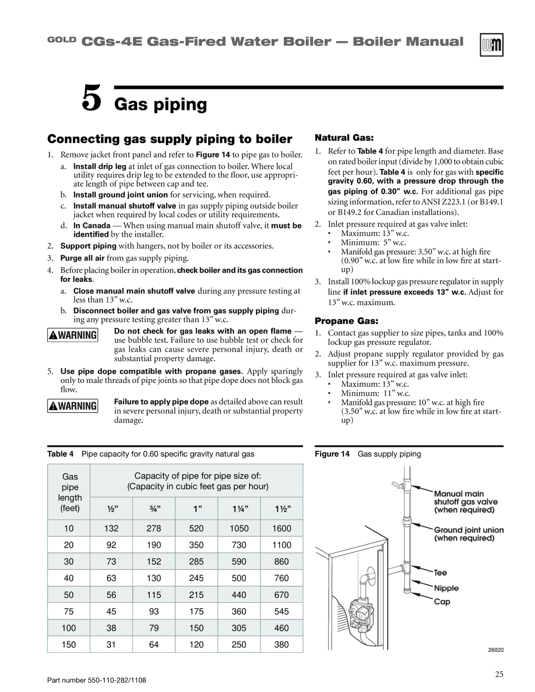
1.Remove jacket front panel and refer to Figure 14 to pipe gas to boiler.
a.Install drip leg at inlet of gas connection to boiler. Where local utility requires drip leg to be extended to the floor, use appropri- ate length of pipe between cap and tee.
b.Install ground joint union for servicing, when required.
c.Install manual shutoff valve in gas supply piping outside boiler jacket when required by local codes or utility requirements.
d.In Canada — When using manual main shutoff valve, it must be identified by the installer.
2.Support piping with hangers, not by boiler or its accessories.
3.Purge all air from gas supply piping.
4.Before placing boiler in operation, check boiler and its gas connection for leaks.
a.Close manual main shutoff valve during any pressure testing at less than 13” w.c.
b.Disconnect boiler and gas valve from gas supply piping dur- ing any pressure testing greater than 13” w.c.
Do not check for gas leaks with an open flame — use bubble test. Failure to use bubble test or check for gas leaks can cause severe personal injury, death or substantial property damage.
5.Use pipe dope compatible with propane gases. Apply sparingly only to male threads of pipe joints so that pipe dope does not block gas flow.
Failure to apply pipe dope as detailed above can result in severe personal injury, death or substantial property damage.
Natural Gas:
1.Refer to Table 4 for pipe length and diameter. Base on rated boiler input (divide by 1,000 to obtain cubic
feet per hour). Table 4 is only for gas with specific gravity 0.60, with a pressure drop through the gas piping of 0.30” w.c. For additional gas pipe sizing information, refer to ANSI Z223.1 (or B149.1 or B149.2 for Canadian installations).
2.Inlet pressure required at gas valve inlet:
•Maximum: 13” w.c.
•Minimum: 5” w.c.
•Manifold gas pressure: 3.50” w.c. at high fire (0.90” w.c. at low fire while in low fire at start- up)
3.Install 100% lockup gas pressure regulator in supply line if inlet pressure exceeds 13” w.c. Adjust for 13” w.c. maximum.
Propane Gas:
1.Contact gas supplier to size pipes, tanks and 100% lockup gas pressure regulator.
2.Adjust propane supply regulator provided by gas supplier for 13” w.c. maximum pressure.
3.Inlet pressure required at gas valve inlet:
•Maximum: 13” w.c.
•Minimum: 11” w.c.
•Manifold gas pressure: 10” w.c. at high fire (3.50” w.c. at low fire while in low fire at start- up)
Table 4 | Pipe capacity for 0.60 specific gravity natural gas |
| Figure 14 Gas supply piping | ||||||
|
|
|
|
|
|
|
|
|
|
Gas |
|
|
| Capacity of pipe for pipe size of: |
|
| |||
pipe |
|
| (Capacity in cubic feet gas per hour) |
|
| ||||
length |
|
|
|
|
|
|
|
| |
|
|
|
|
|
|
|
| ||
(feet) |
| ½” |
| ¾” | 1” | 1¼” |
| 1½” |
|
|
|
|
|
|
|
|
|
|
|
10 |
| 132 |
| 278 | 520 | 1050 |
| 1600 |
|
|
|
|
|
|
|
|
|
|
|
20 |
| 92 |
| 190 | 350 | 730 |
| 1100 |
|
|
|
|
|
|
|
|
|
|
|
30 |
| 73 |
| 152 | 285 | 590 |
| 860 |
|
|
|
|
|
|
|
|
|
|
|
40 |
| 63 |
| 130 | 245 | 500 |
| 760 |
|
|
|
|
|
|
|
|
|
|
|
50 |
| 56 |
| 115 | 215 | 440 |
| 670 |
|
|
|
|
|
|
|
|
|
|
|
75 |
| 45 |
| 93 | 175 | 360 |
| 545 |
|
|
|
|
|
|
|
|
|
|
|
100 |
| 38 |
| 79 | 150 | 305 |
| 460 |
|
|
|
|
|
|
|
|
|
|
|
150 |
| 31 |
| 64 | 120 | 250 |
| 380 |
|
|
|
|
|
|
|
|
|
|
|
Part number
25